
Disturbance compensation mechanism of two axis balance annular shelf

A technology of disturbance compensation and gimbal, which is applied in the direction of aerospace vehicle guides, transportation and packaging, and aircraft parts. The effect of compact structure and small volume of the system

Inactive Publication Date: 2009-04-29
BEIHANG UNIV
View PDF0 Cites 15 Cited by
  • Summary
  • Abstract
  • Description
  • Claims
  • Application Information

AI Technical Summary

Problems solved by technology

However, since the gimbal is installed on the outer shell 8 of the aircraft, the movement of the carrier aircraft will be coupled to the optical axis of the camera, which will cause great interference to the image capture of the camera, thereby greatly reducing the image quality and affecting the work of the visual navigation system

Method used


Image

  • Disturbance compensation mechanism of two axis balance annular shelf
  • Disturbance compensation mechanism of two axis balance annular shelf
  • Disturbance compensation mechanism of two axis balance annular shelf

Examples


Embodiment

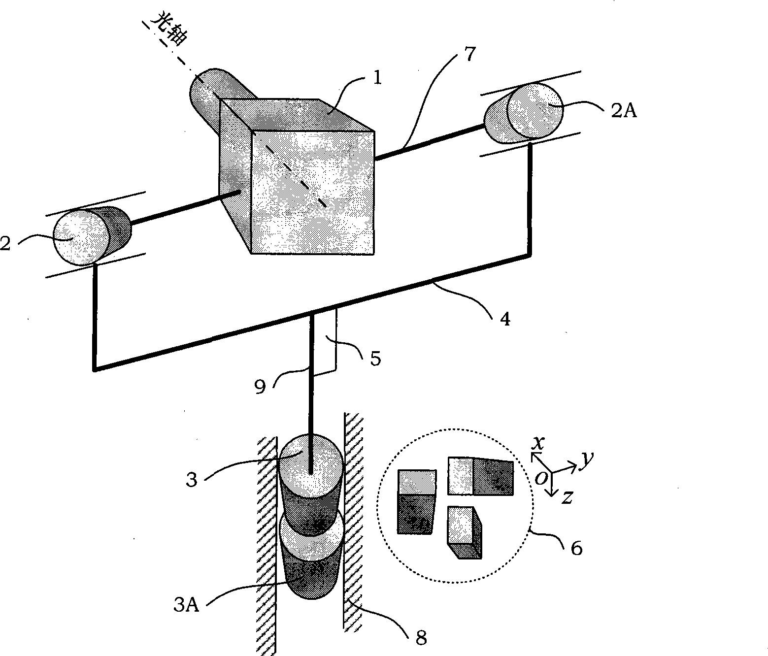
[0038] On a certain type of unmanned aerial vehicle, the front end is equipped with a two-axis balance ring frame with a Cartesian coordinate structure ( figure 1 The structure shown), the camera shoots the scene image at the front of the aircraft, and the three components of the angular velocity of the aircraft are: the x-axis angular velocity component It is a sinusoidal form with an amplitude of 1 radian / s and a frequency of 1.57 radians / s, and the y-axis angular velocity component It is a sinusoidal form with an amplitude of 1 radian / second and a frequency of 6.28 radian / second, and the z-axis angular velocity component It is a sinusoidal form with an amplitude of 1 radian / s and a frequency of 3.14 radians / s, and collects the camera pitch angular velocity ω 7 , camera azimuth velocity ω 9 data, the time response curve is as Figure 4A , Figure 4B shown. When the disturbance compensation device of the present invention is not used, and only the angular velocity fee...


PUM


Abstract

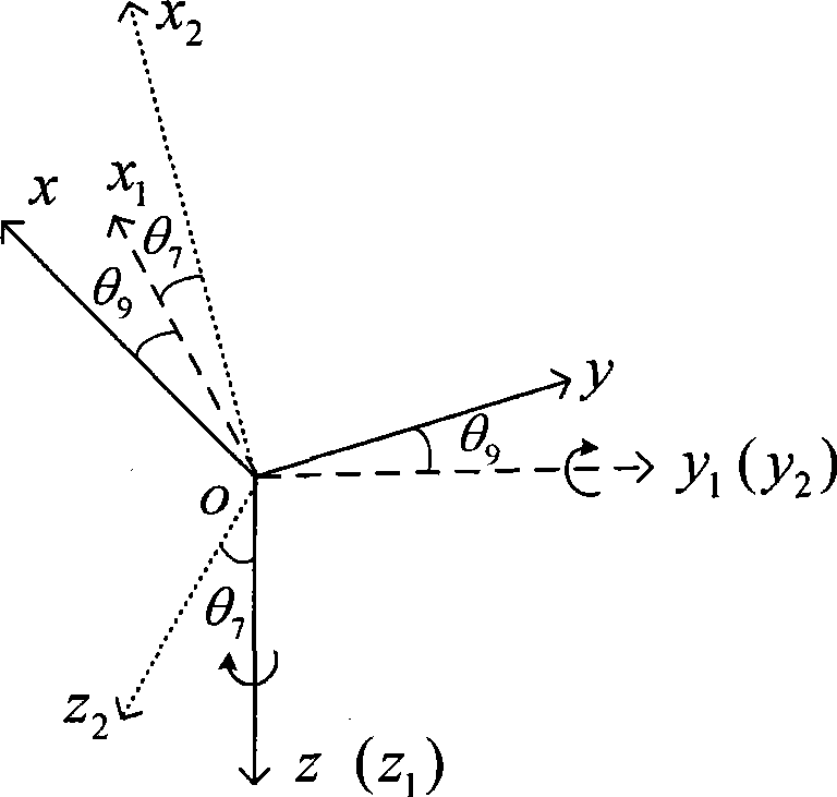
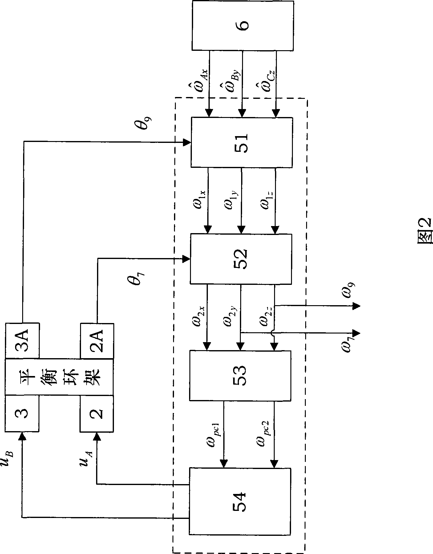
The invention discloses a disturbance compensation device (5) of a two-axle balance ring frame, which is arranged at an external frame axle (9) of the balance ring frame; A motor (2) is coaxially arranged at an internal frame axle (7) with A potentiometer (2A), and the A motor (2) is used for driving the internal frame axle (7) to rotate, thus realizing the pitching movements of a camera (1), and the A potentiometer (2A) is used for producing an internal frame rotation angle Theta7 under the rotating state of the sensitive internal frame axle (7); B motor (3) is coaxially arranged at the external frame axle (9) with B potentiometer (3A), and used for driving the external frame axle (9) to rotate, thus realizing the orientation movements of the camera (1), and the B potentiometer (3A) is used for producing an external frame rotation angle Theta9 under the rotating state of the sensitive external frame axle (9); then a method of coordinate transform is adopted to convert the triaxial angular velocity of an aircraft to the coordinate system of an optical axle of the camera, and then by using the fusion to distribution of F3, three components of the triaxial angular velocity of the aircraft are fused and distributed so as to separate the coupling disturbance caused by the movements of the aircraft to the optical axle of the camera, thus leading the optical axle of the camera to keep stable.

Description

technical field [0001] The invention relates to the control of the optical axis of a camera in a visual navigation system suitable for an aircraft, more particularly, a disturbance compensation device for a two-axis balance ring frame. The disturbance compensation device solves the problem of isolating the coupling disturbance of the aircraft. Background technique [0002] At present, vision-based aircraft navigation, guidance and control is an emerging field that is widely used at home and abroad, especially the vision-based UAV system is one of the focus of research. It mainly installs the camera and its servo system on the aircraft, and has two main applications: on the one hand, it uses the camera and its servo system to process the images of landmarks known in advance, and calculates the position of the UAV aircraft. Attitude parameters are used as the information source for aircraft navigation control. At this time, the camera system is used as a sensor for navigation...

Claims


Application Information

Patent Timeline
Patent Type & Authority Applications(China)
IPC IPC(8): B64G1/24B64D47/08
Inventor 张平董小萌
Owner BEIHANG UNIV
Learn More