Core-loosing highly effective energy-conserving vertical diagonal flow pump

A vertical oblique flow pump, high-efficiency and energy-saving technology, used in non-variable-capacity pumps, components of pumping devices for elastic fluids, pumps, etc. There are no guarantees, size matching is more sensitive, etc., to improve the efficiency of the pump, reduce the manufacturing cost, and reduce low-frequency vibration and shaking.

Inactive Publication Date: 2009-04-29
利欧集团湖南泵业有限公司
View PDF0 Cites 6 Cited by
  • Summary
  • Abstract
  • Description
  • Claims
  • Application Information

AI Technical Summary

Problems solved by technology

[0003] figure 1 Shown is a schematic diagram of the structure of the existing core-pulling vertical diagonal flow pump. The reasons for the low pump efficiency and high manufacturing cost are as follows:
[0004] 1. The bell mouth (1) is a single arc structure. Although the structure is simple, its hydraulic loss is relatively large, and it is sensitive to the position of the pump in the suction pool and the matching with the size of the suction pool
If the matching is not good, it is easy to generate air suction vortex, underwater vortex and swirl flow, which will reduce the efficiency of the pump and even cause the pump to vibrate
[0005] 2. The impeller (4) is an integral open blade, and the casting process is complicated and difficult. Since the blade is a cantilever structure and is relatively thin, the deformation is large during casting, and the flow channel shape line is difficult to meet the design requirements, and the hydraulic performance canno

Method used


Image

  • Core-loosing highly effective energy-conserving vertical diagonal flow pump
  • Core-loosing highly effective energy-conserving vertical diagonal flow pump
  • Core-loosing highly effective energy-conserving vertical diagonal flow pump

Examples


Embodiment Construction

[0036] The present invention will be further described below in conjunction with the accompanying drawings and specific embodiments.

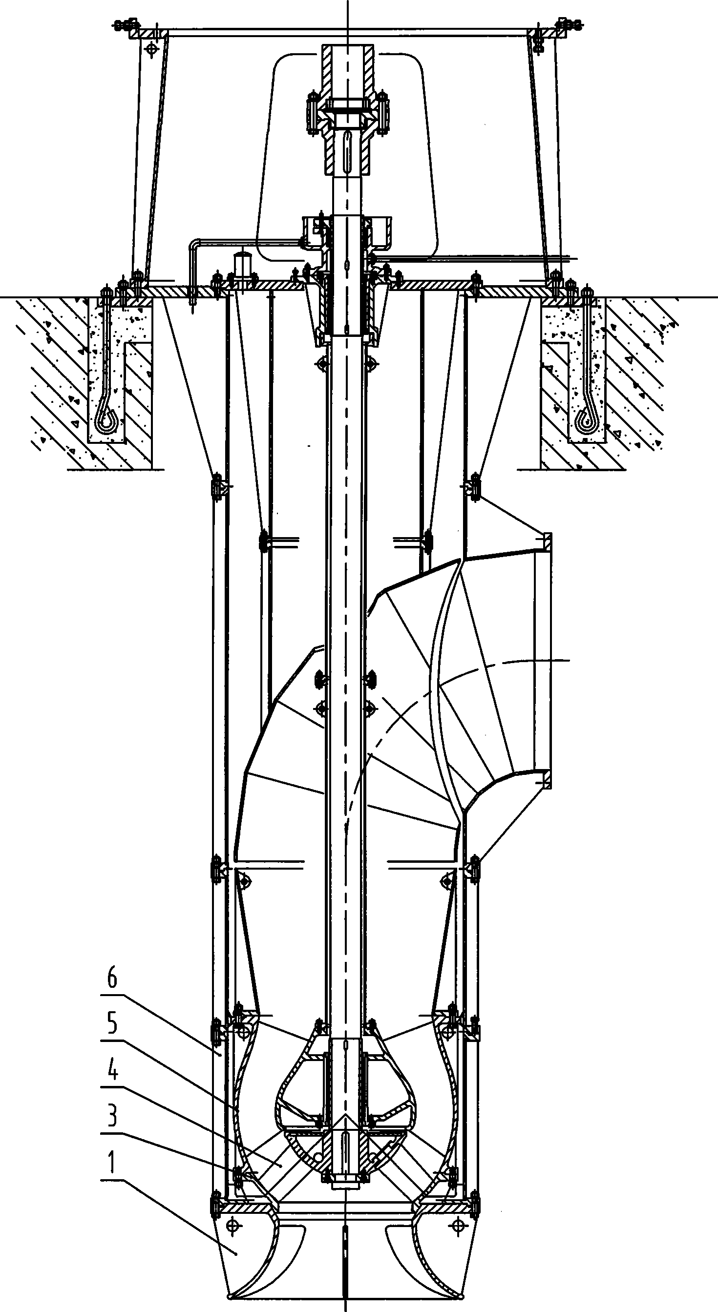
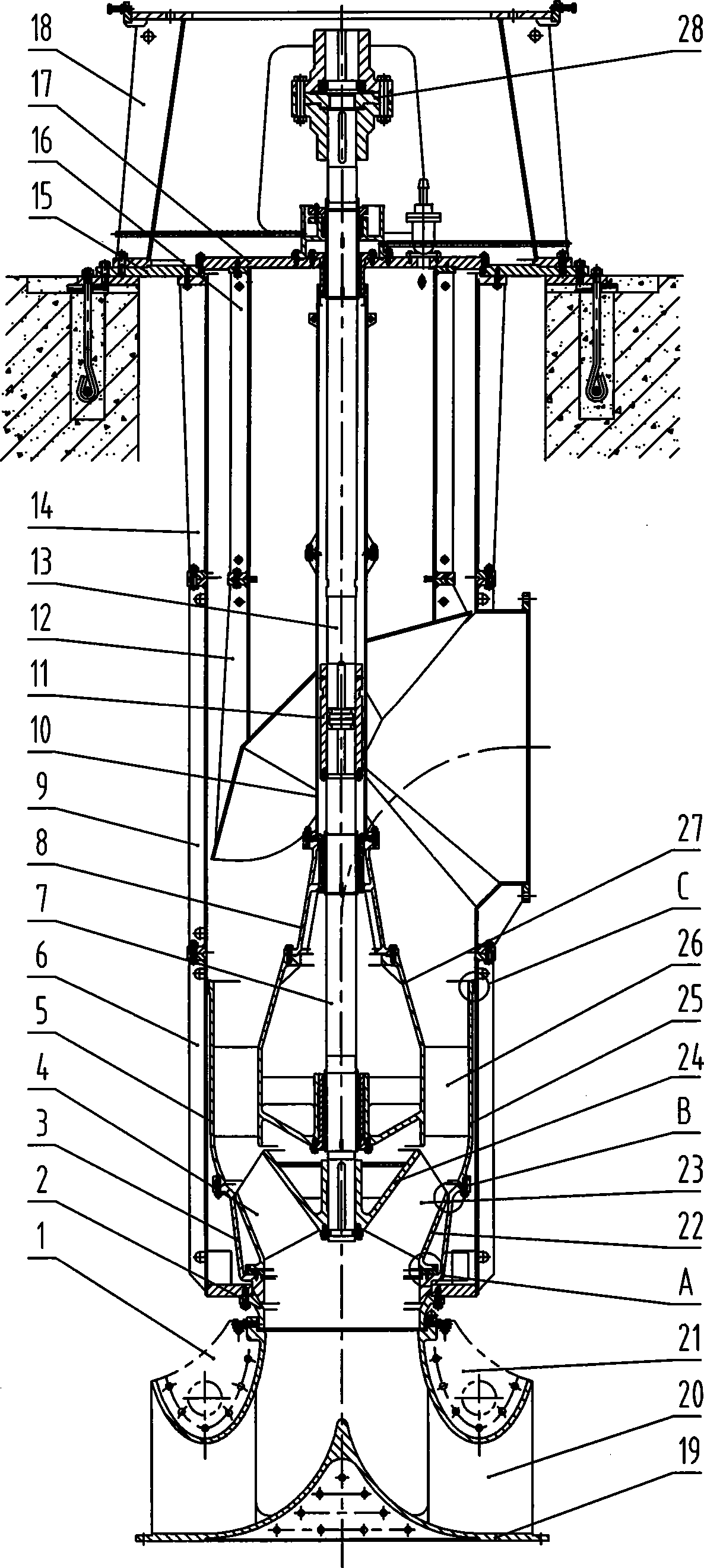
[0037] see figure 2 , the elliptical diversion pier 1 is fixed on the bottom plate of the water inlet pool, the suction pipe 2 is connected to the outlet of the oval diversion pier 1, the suction pipe 2, the lower external connection pipe 6, the water outlet elbow 9, the upper external connection pipe 14, and the support plate 15 , connected together from bottom to top to form the outer cylinder part without core-pulling; impeller chamber 3, guide vane body 5, bearing housing 8, and protective tube 10 are connected together from bottom to top to form the fixed part of the core-pulling part inserted into the outer cylinder In the barrel part; the impeller 4 is installed on the lower main shaft 7, and the upper main shaft 13 and the lower main shaft 7 are connected by the sleeve coupling 11 to form the rotating part of the core-pulling part; Co...


PUM


Abstract

The invention discloses a core-pulling high efficiency energy saving vertical diagonal flow pump, an elliptic diversion pier (1) fixed on the bottom plate of an water input pool, an inhale pipe (2), a lower outer connected pipe (6), a water outlet bending pipe (9), an upper outer connected pipe (14), and a support plate (15) which are connected together down to up to form an outer cylinder part of a non core-pulling part; an impeller chamber (3), a guide vane (5), a bearing seat (8), and a protection pipe (10) which are connected down to up to form the fixed part of the core-pulling part; an impeller (4) fixed on a lower main shaft (7), an upper main shaft (13), and the lower main shaft (7) which is connected with the upper main shaft (13) through a sleeve coupling (11) to form the rotation part of the core-pulling part; a diversion casing (12), a connection pipe (16), and a cover plate (17) which are connected together down to up and fixed on the support plate; and a motor base (18) fixed on the support plate (15). The invention has high efficiency, simple structure, low manufacture cost, stable operation, convenient maintenance, and reliable safety.

Description

technical field [0001] The invention relates to a diagonal flow pump, in particular to a core-pulling type high-efficiency energy-saving vertical diagonal flow pump. Background technique [0002] Vertical diagonal flow pumps are widely used, especially with the development of the power industry, vertical diagonal flow pumps that can be used as circulating water pumps in power plants are also developing towards large diameter, large flow, and high power. Thermal power plants are important enterprises that produce and supply electric energy, and are also large consumers of electric energy. The circulating water pump is one of the important auxiliary machines in thermal power generation equipment, and its power consumption accounts for about 1% of the power generation capacity of the main engine. The environment has significant economic and social benefits. [0003] figure 1 Shown is a schematic diagram of the structure of the existing core-pulling vertical diagonal flow pum...

Claims


Application Information

Patent Timeline
IPC IPC(8): F04D29/40F04D29/20F04D29/24
Inventor 吴波
Owner 利欧集团湖南泵业有限公司
Why Eureka
Try Eureka