
Amplifier tube screening instrument

A power tube and triode technology, which is applied in the field of screening instruments for testing the performance of power tube parameters, can solve the problems of inaccurate parameters measured by digital multimeters, inability to reuse power MOS tubes, affecting product consistency and reliability, etc. High efficiency, easy maintenance, and the effect of reducing maintenance costs

Inactive Publication Date: 2009-04-29
TIANJIN SONGZHENG ELECTRONICS
View PDF0 Cites 6 Cited by
  • Summary
  • Abstract
  • Description
  • Claims
  • Application Information

AI Technical Summary

Problems solved by technology

[0002] Due to its excellent performance, power MOS tubes have been widely used in electronic ballasts, energy-saving lamps and various circuits. However, the testing, screening, and matching of power MOS tubes have always been difficult; and from the circuit board The disassembled power MOS tube also needs to be tested for the performance of various parameters. If the turn-on voltage, withstand voltage value, transconductance, channel resistance, and input capacitance are all within the specified range, it can be used again, thereby saving costs. Now In the existing technology, digital multimeters are often used to measure the performance of various parameters of power MOS tubes. The parameters measured by digital multimeters are inaccurate, and the efficiency is low, and the power MOS tubes cannot be reused, which will increase the cost of the product virtually; due to the lack of Corresponding inspection methods, many companies cannot effectively monitor quality, which seriously affects the consistency and reliability of products

Method used


Image

  • Amplifier tube screening instrument
  • Amplifier tube screening instrument
  • Amplifier tube screening instrument

Examples


Embodiment Construction

[0024] The technical solutions of the present invention will be described in detail below in conjunction with the specific circuit diagrams given in the accompanying drawings.

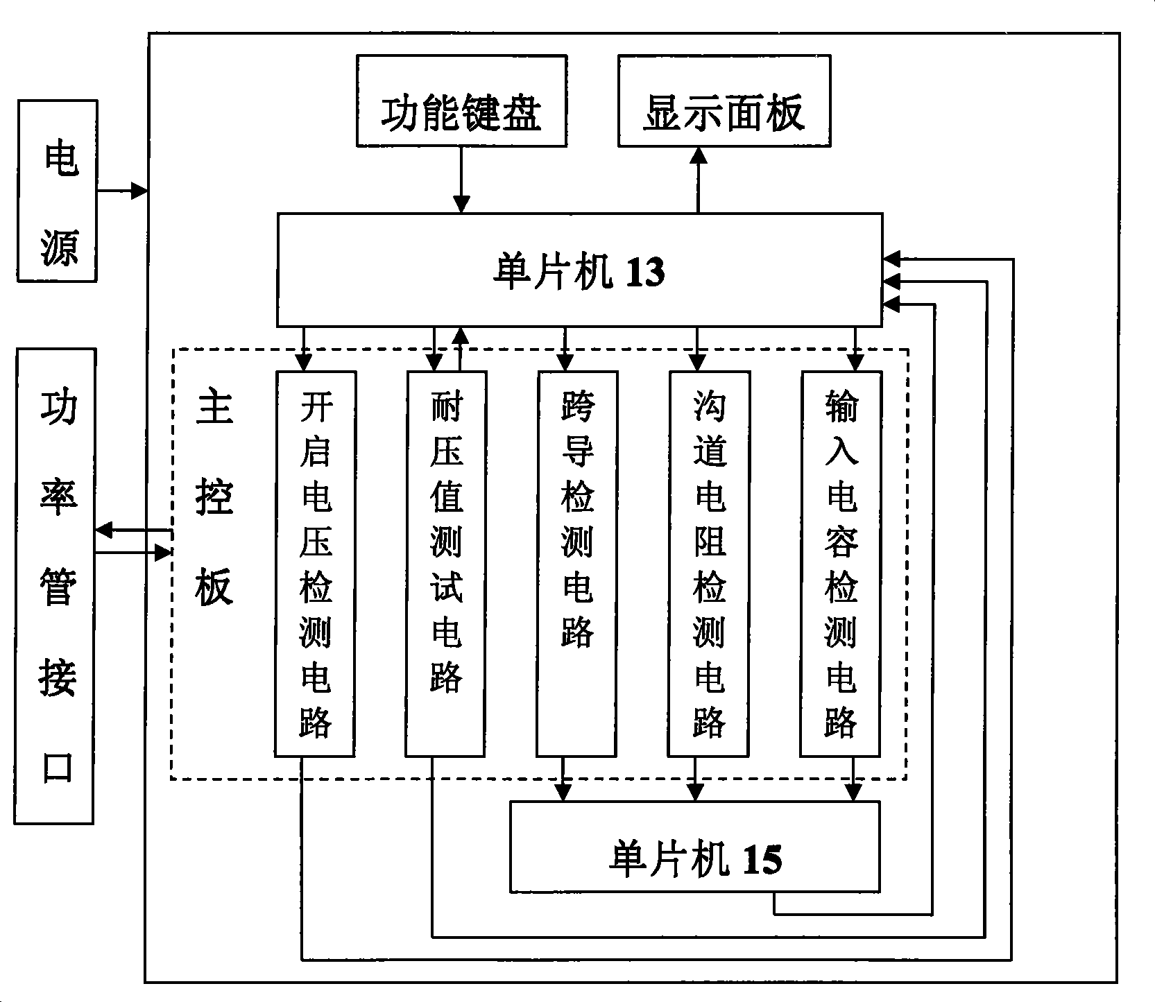
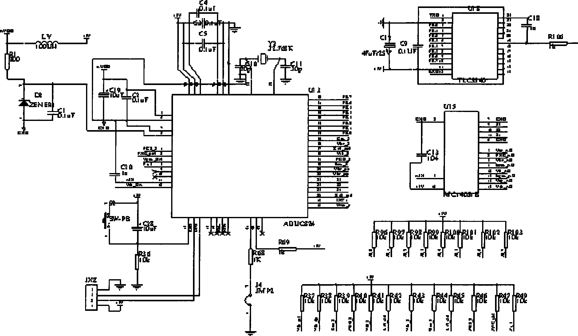
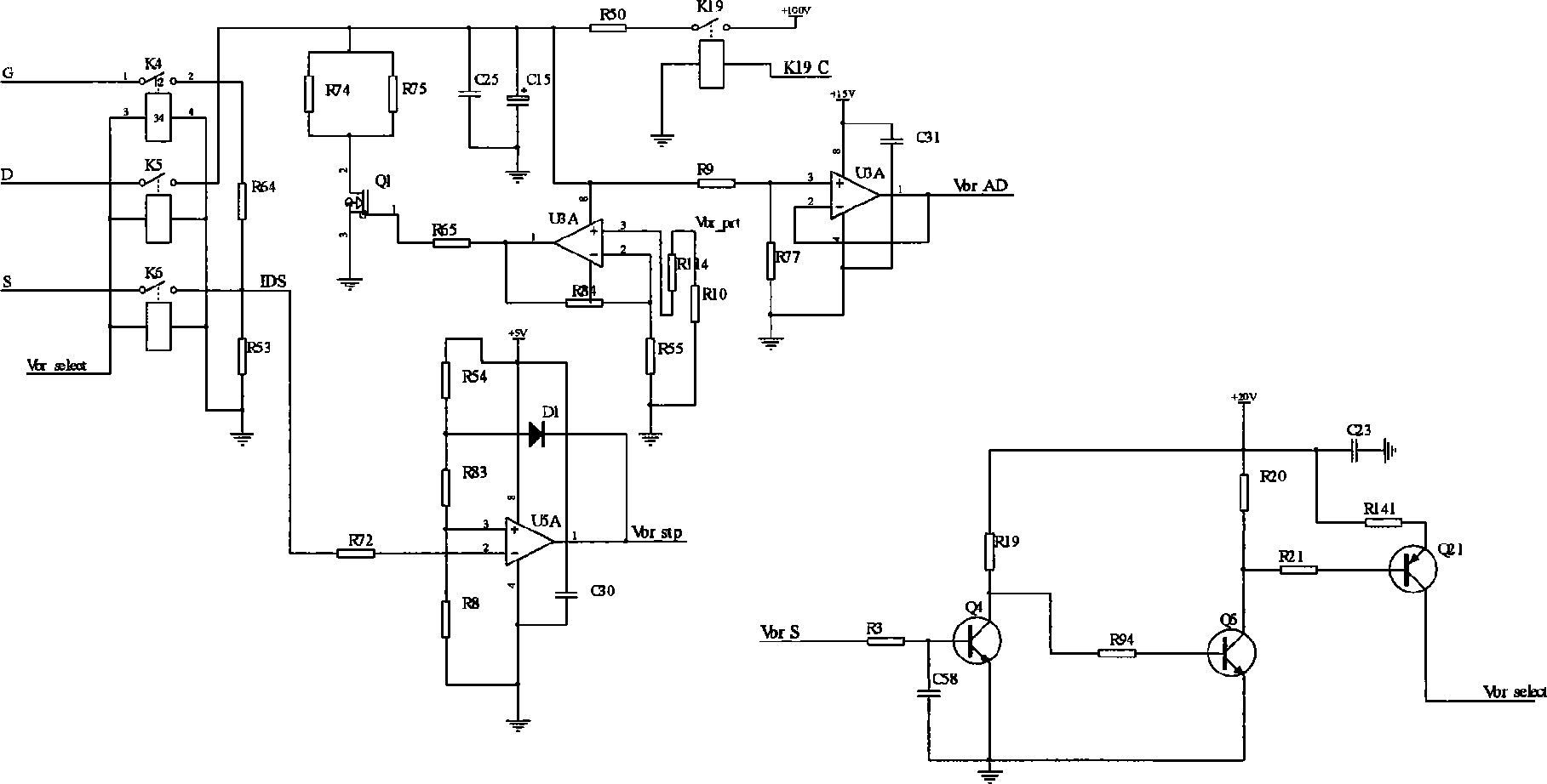
[0025] see figure 1 , 2 、3

[0026] Single-chip microcomputer 13 models are ADUC824, produced by U.S. AD Company, as central processing unit of the present invention; Single-chip microcomputer 18 models are TLC5540, 8 high-speed A / D converters released by U.S. Texas Instruments; Single-chip microcomputer 15 models are MC14051B, manufacturer It is ON SEMICONDUCTOR, which can be replaced by CD4051 and HC4051 as an analog relay.

[0027] The power supply voltages required by the present invention are respectively +5V, +15V, +20V, +100V, which are converted by a linear voltage stabilizing chip.

[0028] The relay driving circuit in the described circuit, during normal state, the single-chip microcomputer 13 outputs V th_ S is high level, making Q2 saturated and conducting, making Q3 cut off, Q20 also c...


PUM


Abstract

The invention discloses a power tube screening instrument. The screen instrument comprises a power source, a functional keyboard, a display panel, a singlechip 13, a singlechip 15 and a main control panel, wherein the main control panel comprises a withstand voltage testing circuit. The connection mode is as follows: the singlechip 13 inputs signals to a relay driving circuit in the withstand voltage testing circuit; pole c of a dynatron Q21 is connected with one end of each of a relay coil respectively; the other ends of the relay coils are earthed; poles G, D and S corresponding to the interface of the power tube are connected with one end of each of relays K4, K5 and K6 respectively; a voltage comparator U5A outputs signals to the singlechip 13; an amplifier U3B magnifies Vbrprt signals to make FET Q1 conduct; K19 is actuated through the relay driving circuit; a high voltage power supply outputs voltage to charge a capacitor through a resistor R50; and a voltage follower U3A outputs signals to the singlechip 15. The power tube screening instrument has the advantages of high efficiency of testing, high precision, good stability, strong anti-interference capability, and is suitable to be used in a workshop.

Description

technical field [0001] The invention relates to a testing device in the electronic field, in particular to a screening instrument for testing the parameter performance of a power tube. Background technique [0002] Due to its excellent performance, power MOS tubes have been widely used in electronic ballasts, energy-saving lamps and various circuits. However, the testing, screening, and matching of power MOS tubes have always been difficult; and from the circuit board The disassembled power MOS tube also needs to be tested for the performance of various parameters. If the turn-on voltage, withstand voltage value, transconductance, channel resistance, and input capacitance are all within the specified range, it can be used again, thereby saving costs. Now In the existing technology, digital multimeters are often used to measure the performance of various parameters of power MOS tubes. The parameters measured by digital multimeters are inaccurate, and the efficiency is low, an...

Claims


Application Information

Patent Timeline
IPC IPC(8): G01R31/26G01R31/00
Inventor 孔昭松于新昌杨新璇郭世荣刘海
Owner TIANJIN SONGZHENG ELECTRONICS
Learn More