Carbon cloth tension automatic control device in low temperature carbonization furnace system

An automatic control device, low-temperature carbonization technology, applied in non-electric variable control, mechanical pressure/force control, control/regulation system, etc., can solve the problem of no overshoot PID algorithm feedback control strategy, and limit the research and development of graphitized fibers and promotion and application, to achieve the effect of fast response, good stability and convenient process operation

Inactive Publication Date: 2009-04-29
SHANGHAI SXCARBON TECH
View PDF3 Cites 10 Cited by
  • Summary
  • Abstract
  • Description
  • Claims
  • Application Information

AI Technical Summary

Problems solved by technology

[0005] After searching, it was found that the Chinese patent application of Mitsubishi Rayon Co., Ltd., titled: Acrylonitrile-based precursor fiber for carbon fiber and its preparation method, CN200410006862.1, application date 1999.07.22, publication date 2004.10.13, This technology discloses a method for preparing an acrylonitrile-based precursor fiber of carbon fiber. The disadvantage of this technology is that it must be heated and stretched through a roller for many times to increase the draw ratio of carbon fiber.
The above factors have seriously limited the development and application of graphitized fibers in my country.
[0007] There are obvious problems and deficiencies in the above-mentioned existing technologies. Since the carbon cloth will shrink with the escape of volatile matter in the low-temperature carbonization furnace, even if the above-mentioned three existing technologies are combined, the problem based on the no-overshoot PID algorithm cannot be solved. Technical Difficulties of Feedback Control Strategies

Method used


Image

  • Carbon cloth tension automatic control device in low temperature carbonization furnace system
  • Carbon cloth tension automatic control device in low temperature carbonization furnace system

Examples


Embodiment Construction

[0021] The embodiments of the present invention are described in detail below in conjunction with the accompanying drawings: this embodiment is implemented under the premise of the technical solution of the present invention, and detailed implementation methods and processes are provided, but the protection scope of the present invention is not limited to the following implementations example.

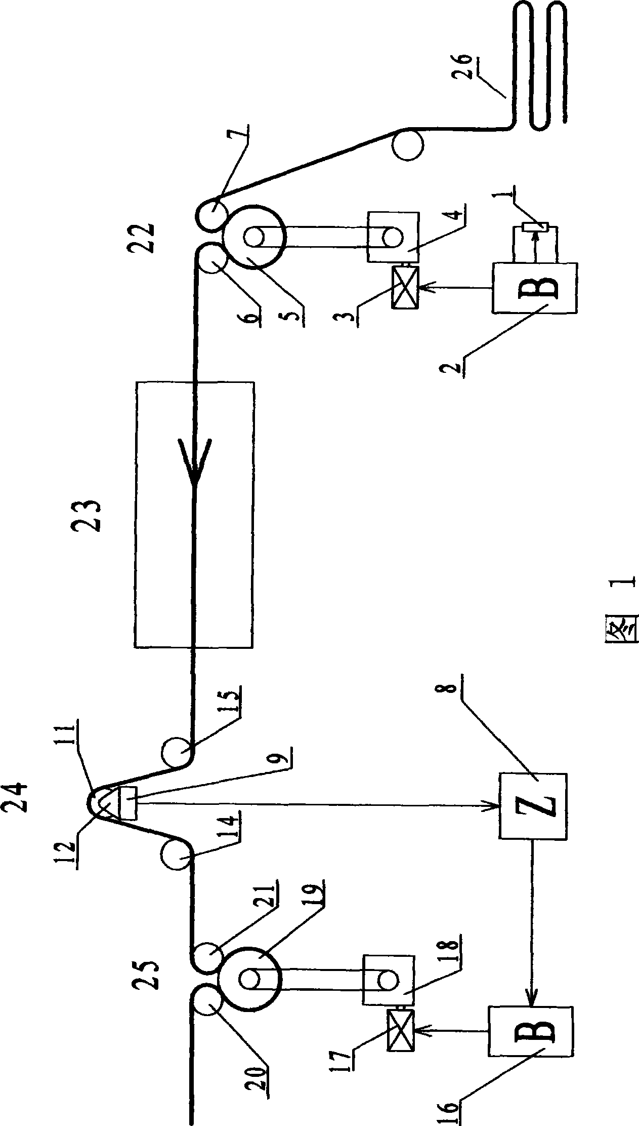
[0022] As shown in Figure 1, this embodiment includes: potentiometer 1, inlet frequency conversion controller 2, tension controller 8, outlet frequency conversion controller 16, inlet drive roller 22, tension roller 24, and outlet drive roller 25, wherein: the inlet drive The roller 22 is placed in front of the low-temperature carbonization furnace 23, the potentiometer 1 is connected to the inlet frequency conversion controller 2 to control the inlet drive roller 22, and the tension roller 24 and the outlet drive roller 25 are placed in sequence behind the low-temperature carbonization...


PUM

PropertyMeasurementUnit
strengthaaaaaaaaaa
modulusaaaaaaaaaa

Abstract

The invention relates to an automatic carbon cloth tension controlling device in a carbon cloth low-temperature carbide furnace system used by a fuel battery in the automatic control field. The device comprises a potentiometer, an inlet frequency variation controller, an inlet driving roller, a tension controller, a tension roller, an outlet frequency variation controller and an outlet driving roller. The inlet driving roller is positioned in front of a low-temperature carbide furnace; the inlet frequency variation controller, the potentiometer and the inlet driving roller form a closed loop feedback chain; the tension roller and the outlet driving roller are sequentially positioned behind the low-temperature carbide furnace; the tension controller is respectively connected with the tension roller and the outlet frequency variation controller; and the outlet frequency variation controller is connected with the outlet driving roller to output the carbon cloth. A tension sensor in the invention measures and obtains an instant tension value of the carbon cloth and is controlled by a feedback closed loop so that the carbon cloth tension control achieves high accuracy, satisfactory stability and fast response. Manual adjustment of the potentiometer can stabilize the invention in a new and balanced feedback loop so as to perform fine adjustment to the carbon cloth of different materials and to facilitate technical operations.

Description

technical field [0001] The invention relates to an electromechanical automatic control device in the field of automatic control, in particular to a carbon cloth tension automatic control device in a fuel cell carbon cloth low-temperature carbonization furnace system. Background technique [0002] The tension of carbon cloth is a very important parameter in the low-temperature carbonization process of carbon cloth for fuel cells, which directly affects the strength of carbon cloth. The commonly used carbon fiber production process in the world is to pre-oxidize polyacrylonitrile fibers and then carbonize them at 1000-1500 ° C. If treated at a higher temperature, graphite fibers or graphitized carbon fibers can be obtained. At present, graphitized carbon fiber products are mainly imported from abroad. One of the keys to the production of graphitized carbon fiber is whether the special production equipment can meet the production process requirements. The existing improved pro...

Claims


Application Information

Patent Timeline
Patent Type & Authority Applications(China)
IPC IPC(8): G05D15/01D06C7/04
Inventor 朱亦华许晓峰沈曙光张良年
Owner SHANGHAI SXCARBON TECH
Why Eureka
Try Eureka