
High-pressure fuel supply pump and the manufacturing method

一种高压燃料、供给泵的技术,应用在燃料喷射泵、制造工具、燃料喷射装置等方向,能够解决尺寸变化、接合强度不充分、流体密封性不充分等问题,达到强固接合力、大焊接接合面积、实现密封功能的效果

Inactive Publication Date: 2009-05-06
HITACHI LTD
View PDF5 Cites 24 Cited by
  • Summary
  • Abstract
  • Description
  • Claims
  • Application Information

AI Technical Summary

Problems solved by technology

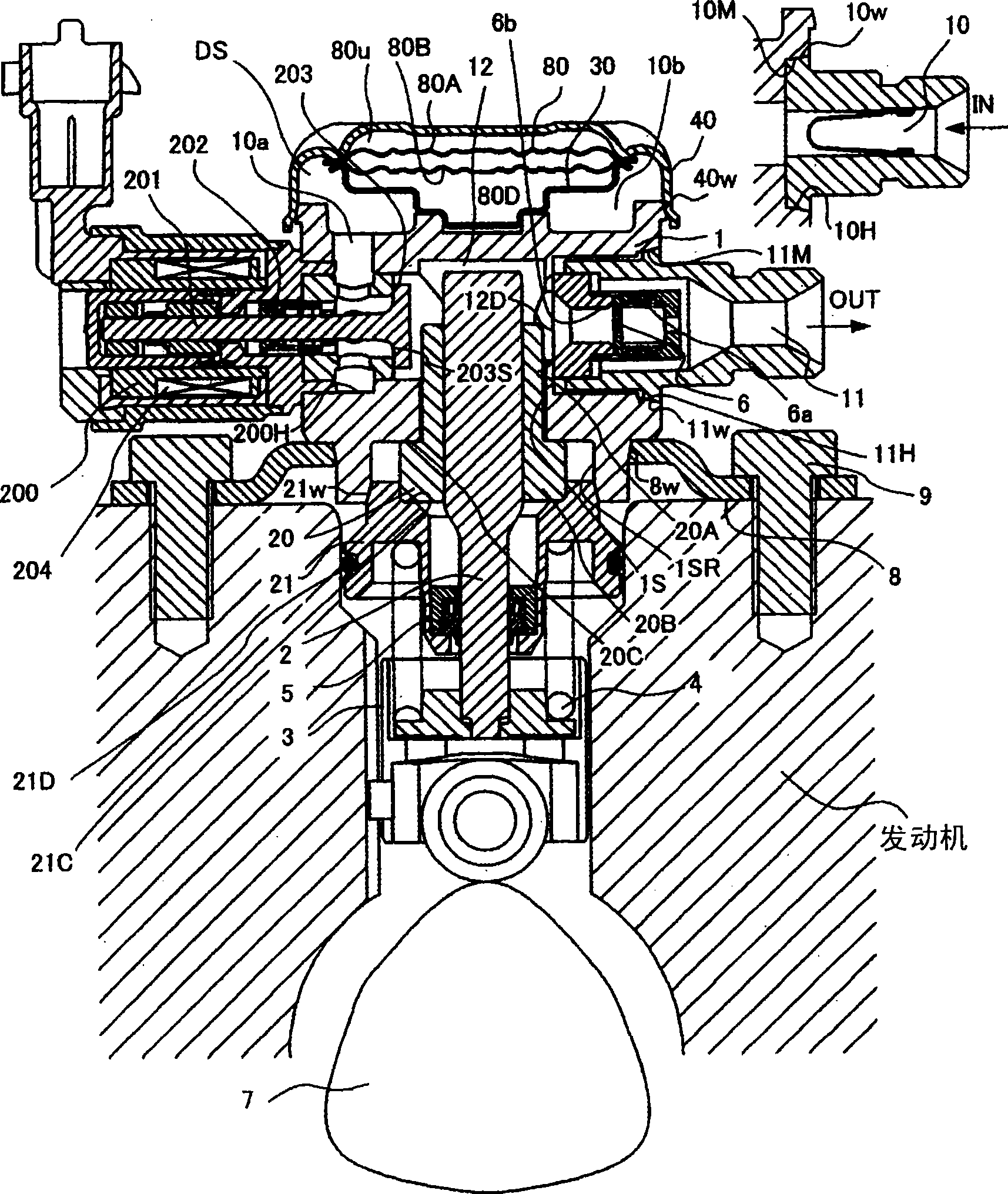
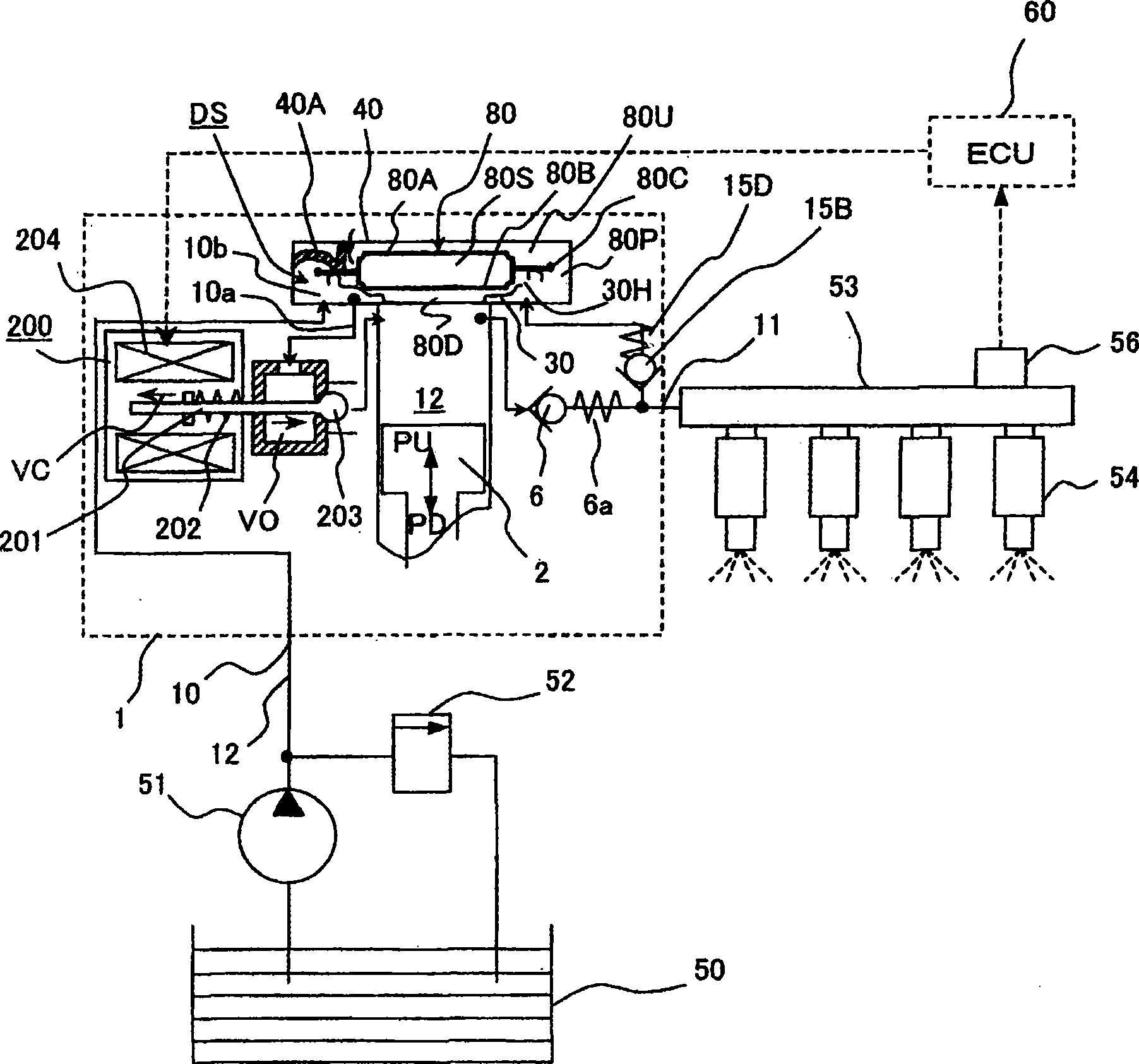
[0010] In the high-pressure fuel supply pump, there is a problem that, for example, the pump body and the pump casing always have a place where two cylindrical members are fitted and joined together.
However, in these joint structures, the fluid tightness and joint strength are not sufficient. Especially in the case of laser welding, the composition of the material itself changes due to heat, and the magnetic properties change randomly before and after joining. Therefore, It is not suitable for the part of the magnetic circuit. In addition, it causes the dimensional change of the member due to thermal deformation before and after joining, and cannot maintain the original design size.

Method used


Image

  • High-pressure fuel supply pump and the manufacturing method
  • High-pressure fuel supply pump and the manufacturing method
  • High-pressure fuel supply pump and the manufacturing method

Examples


Embodiment approach 1

[0163] A joint structure of two members, a basic technology of joining a joint member and a non-joint member by welding, wherein the joint surface of the above two members has a conical joint surface, sandwiching the joint surface, formed along the joint The plastic flow area of ​​the above two components on the surface.

Embodiment approach 2

[0165] A joint structure of two members is the basic technique described in Embodiment 1, wherein a diffusion bonded region of the two members is formed in a region including the joint surface sandwiched between plastic flow regions of the two members.

Embodiment approach 3

[0167] A joint structure of two members, which is the basic technique described in Embodiment 1, wherein at least one of the large-diameter side end or the small-diameter side end of the conical joint surface is provided with the large-diameter side end or the small-diameter side Any one of the annular cavity, the annular groove or the annular recess facing any one of the ends.


PUM


Abstract

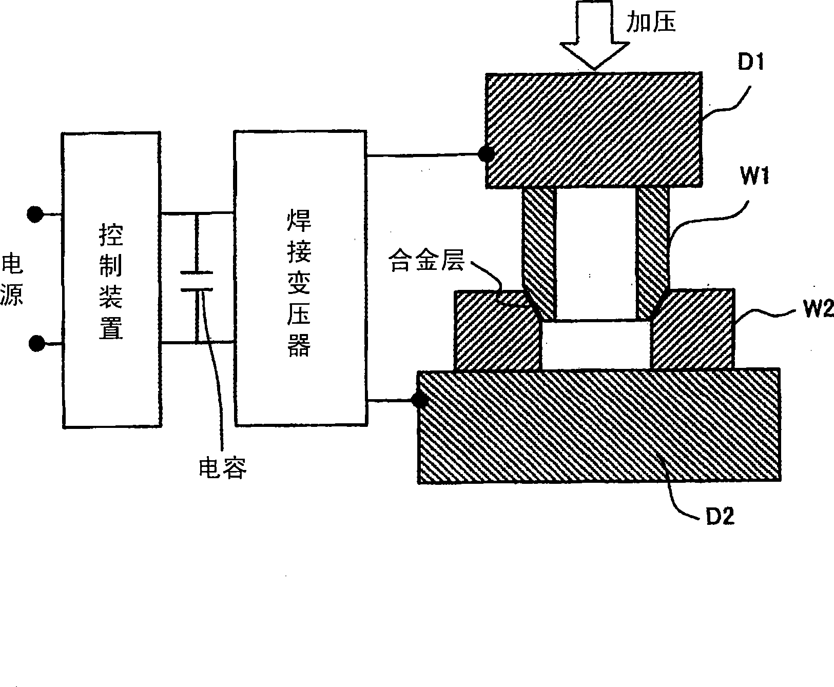
An object of this invention is to provide such a welded structure of and welding method for two metallic parts fitted together at a tubular section in a high-pressure fuel supply pump, that enables rapid joining of both metallic parts by staking (press-fitting included), screw fastening, and / or laser welding, offers high welding strength and sufficient fluid sealability, and keeps the metallic materials free from thermal changes in composition. While an electric current is supplied to any one of the welding connection surfaces formed between a pump housing and cylinder in a high-pressure fuel supply pump, between the pump housing and an installation flange, between the pump housing and an intake or discharge joint, between the pump housing and a pulsation-absorbing damper cover, between the pump housing and a relief valve mechanism, and between the pump housing and an electromagnetically driven intake valve mechanism, the particular two sections are pressed against each other to generate, along the connection surface, a plastic flow not causing melting or fusion due to heat, and form a diffusion-weld region at the connection surface by using the plastic flow and the application of the pressure.

Description

technical field [0001] The present invention relates to a high-pressure fuel pump and a manufacturing method thereof, and particularly relates to a joining structure in which two metal members are fitted in an annular or cylindrical portion and welded at the fitting portion. Background technique [0002] JP-A-2005-342782 and JP-A-2004-17048 are known as techniques for fitting a cylindrical member into a hole of a cylindrical portion and welding two metal members. [0003] According to this, a technique is described in which two metals are joined by applying current to a fitting portion while applying pressure. [0004] On the other hand, the joint structure of the pump body and the pump casing of the high-pressure fuel pump is known as follows: fixing of fasteners at the sealing part for forming metal contact between the two (WO2002 / 055881 International Publication) and pump After the outer periphery is sealed by pressing, the end of the pump body and the pump casing are ri...

Claims


Application Information

Patent Timeline
Patent Type & Authority Applications(China)
IPC IPC(8): F02M59/02B23K11/02
CPCB23K11/16B23K11/26B23K2203/02B23K2201/04F04B1/0404F02M59/02B23K33/008F04B53/168F02M59/48B23K33/006F02M59/485B23K20/023F02M2200/8084B23K2101/04B23K2103/02
Inventor 栋方明广町村英纪细川和孝
Owner HITACHI LTD
Learn More