Mineral fluid high-pressure delivery pump

A technology of high-pressure transportation and minerals, which is applied to parts, pumps, and pump components of pumping devices for elastic fluids, which can solve the problems of crankshafts such as huge mass, mass, bulky, and inconvenient transportation, and achieve volume reduction and The effect of weight, compact and simple structure, convenient start and stop

Inactive Publication Date: 2009-05-06
HUBEI JINGGONG SCI & TECH
View PDF0 Cites 5 Cited by
  • Summary
  • Abstract
  • Description
  • Claims
  • Application Information

AI Technical Summary

Problems solved by technology

Its disadvantages are: 1. The crankshaft has a huge mass, and it is inconvenient to start and stop; 2. The crank-link mechanism has many parts, high manufacturing cost, high quality and volume, large floor space, and inconvenient transportation; 3. Replacement of the piston (Diaphragm) The hydraulic oil must be drained completely, otherwise the hydraulic oil will enter the mineral fluid being transported; 4. The equipment must be equipped with a hydraulic cooling system to transport high-pressure mineral fluid (such as coal-water slurry) for a long time. As for the larger volume, the higher cost

Method used


Image

  • Mineral fluid high-pressure delivery pump
  • Mineral fluid high-pressure delivery pump

Examples


Embodiment

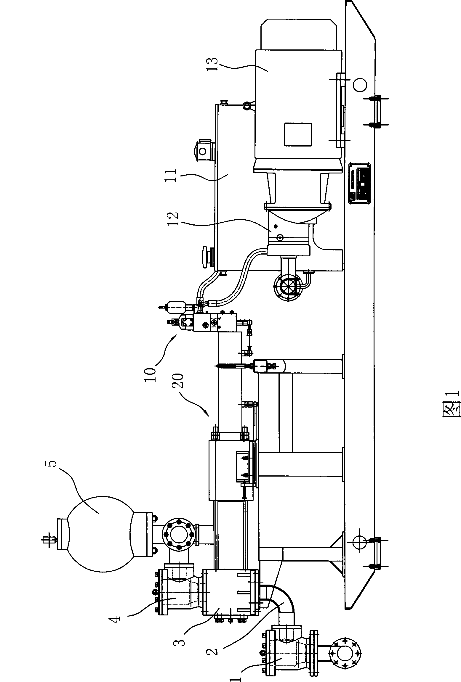
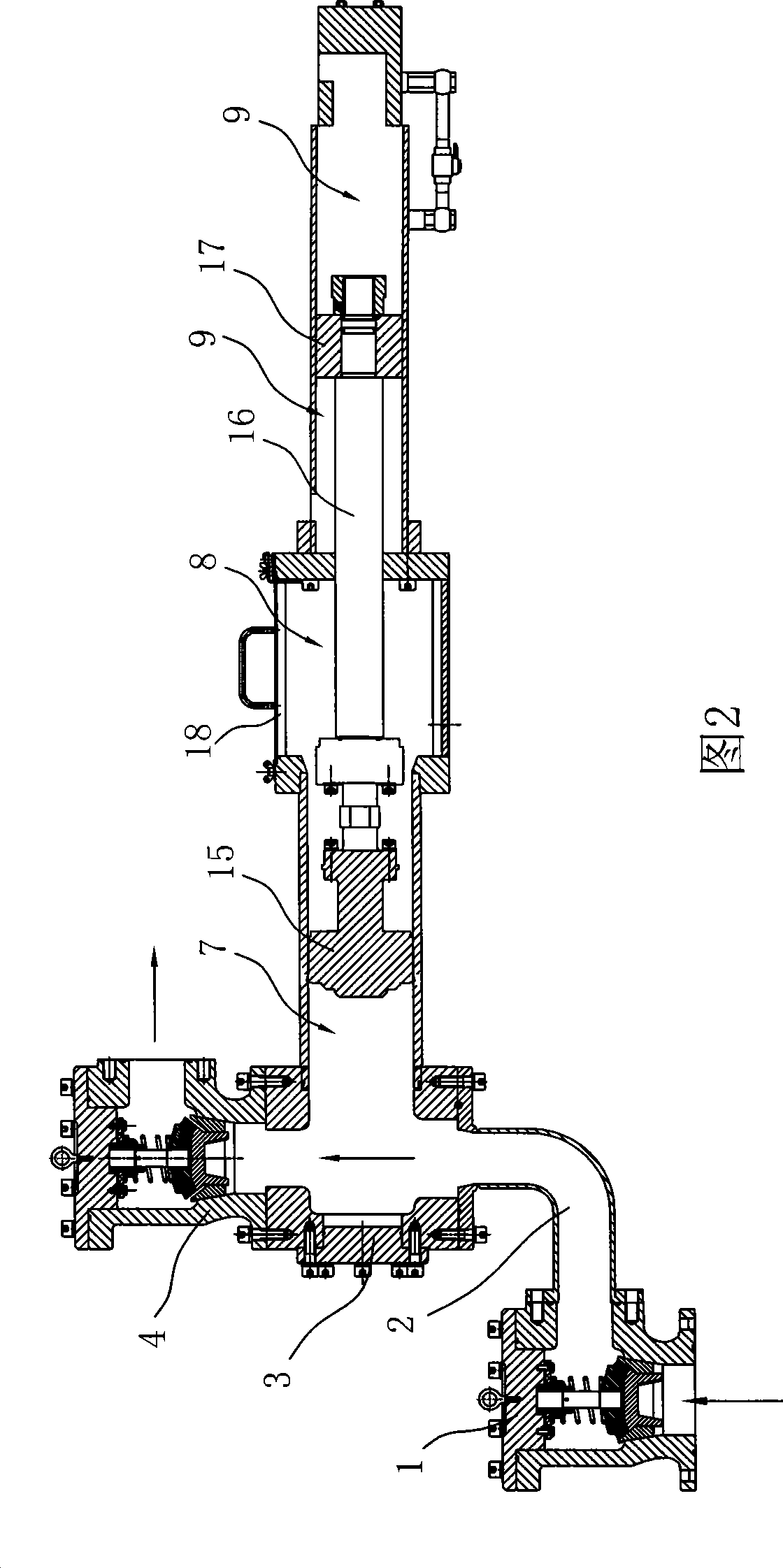
[0015] Embodiment: mineral fluid high-pressure delivery pump, as shown in Figure 1 and Figure 2, it comprises pump body 20, is located at the piston 15 in the pump body 10, and the delivery cylinder 7 that cooperates with piston 15, is connected with piston 15 Piston drive shaft 16, the drive mechanism for driving the action of the piston drive shaft 16, is characterized in that the pump body 20 is provided with a drive cylinder 9 that matches the drive mechanism, and the drive cylinder 9 is provided with a drive cylinder that is connected to the piston drive shaft 16. Piston drive shaft driver 17, a washing cooling chamber 8 is provided between the delivery cylinder 7 and the driving cylinder 9, one end of the piston driving shaft 16 is detachably connected to the piston 15, and the other end passes through the washing cooling chamber 8 and enters the driving cylinder 9 is connected with the piston drive shaft driver 17. The driving mechanism is a hydraulic driving mechanism....


PUM


Abstract

The invention relates to a mineral fluid high-pressure delivery pump, which comprises a pump body, a piston which is arranged inside the pump body, a delivery cylinder which is matched with the piston, a piston driving shaft which is connected with the piston, and a driving mechanism which drives the piston driving shaft to operate, wherein the inside of the pump body is provided with a driving cylinder which is matched with the driving mechanism; the inside of the driving cylinder is provided with a driving piece of the piston driving shaft which is connected with the piston driving shaft; a cleaning and cooling chamber is arranged between the delivery cylinder and the driving cylinder; and one end of the piston driving shaft is detachably connected with the piston and the other end of the piston driving shaft passes through the cleaning and cooling chamber, and enters into the driving cylinder to be connected with the driving piece of the piston driving shaft. The mineral fluid high-pressure delivery pump has the advantages that: firstly, due to adoption of the full hydraulic-driven mineral fluid (such as coal water slurry) pump, the operation is simple and convenient, and starting and stopping are convenient; secondly, due to arrangement of the cleaning and cooling chamber, the phenomenon of pollution due to the fact that hydraulic oil enters into mineral fluid is avoided when the piston is replaced; and thirdly, the cleaning and cooling chamber also has the functions of lubricating and cooling when the piston is operated for a long time.

Description

【Technical field】 [0001] The invention relates to a conveying pump, in particular to a mineral fluid high-pressure conveying pump provided with a washing cooling chamber and a hydraulic drive mechanism for driving a piston. 【Background technique】 [0002] Various existing high-pressure mineral fluid (such as coal water slurry) pumps (also known as diaphragm pumps) work in the way that the motor drives the crank connecting rod mechanism, and then drives the crankshaft to drive the single-acting plunger cylinder to move, and then drives the piston (diaphragm) to act. Reciprocating motion, thereby pushing the conveying medium to move. Its disadvantages are: 1. The crankshaft has a huge mass, and it is inconvenient to start and stop; 2. The crank-link mechanism has many parts, high manufacturing cost, high quality and volume, large floor space, and inconvenient transportation; 3. Replacement of the piston (Diaphragm) The hydraulic oil must be drained completely, otherwise the h...

Claims


Application Information

Patent Timeline
Patent Type & Authority Applications(China)
IPC IPC(8): F04B15/02F04B53/22F04B53/14F04B53/00
Inventor 邵志明袁伏虹丁均才
Owner HUBEI JINGGONG SCI & TECH
Why Eureka
Try Eureka