Probe-fixing and example-oscillating non-micro rod scanning force microscope lens

An oscillating, microscope technology, applied in the field of scanning probe microscopy, can solve the problems of difficulty in the manufacture of scanning force microscopy probes, inability to use microrodless probes, etc., to improve atomic resolution, reduce probe costs, and improve measurement. The effect of sensitivity

Inactive Publication Date: 2009-05-06
UNIV OF SCI & TECH OF CHINA
View PDF0 Cites 4 Cited by
  • Summary
  • Abstract
  • Description
  • Claims
  • Application Information

AI Technical Summary

Problems solved by technology

[0003] In order to overcome the difficulties in the manufacture of scanning force microscope probes in the prior art and the inability to use micro-rod probes, a micro-rod-free scanning force microscope mirror body is provided w

Method used


Image

  • Probe-fixing and example-oscillating non-micro rod scanning force microscope lens
  • Probe-fixing and example-oscillating non-micro rod scanning force microscope lens
  • Probe-fixing and example-oscillating non-micro rod scanning force microscope lens

Examples


Embodiment 1

[0029] Example 1: The basic probe is fixed and the sample is oscillating without a microrod scanning force microscope lens body.

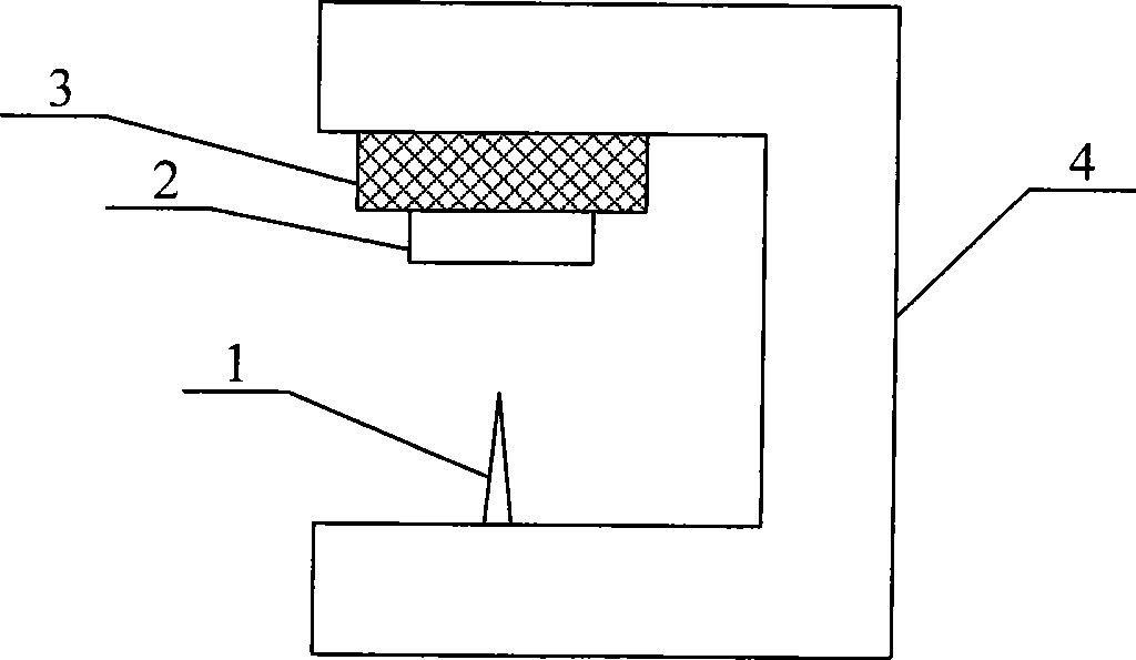
[0030] figure 1 It is a schematic diagram of the structure of the basic probe-fixed and sample-oscillating microrodless scanning force microscope mirror body. The positioner 4 is arranged between the probe 1 and the vibrator 3 , and the probe 1 points to the sample 2 fixed on the vibrator 3 .

[0031] During operation, the positioner 4 is used for positioning, scanning, and probe-sample gap adjustment between the probe 1 and the sample 2 . The variation of the force between probe 1 and sample 2 is given by the variation of the dynamic eigenfrequency of the vibrator.

Embodiment 2

[0032] Example 2: Using the XYZ positioning piezoelectric tube with the probe fixed and the sample oscillating without a microrod scanning force microscope mirror body.

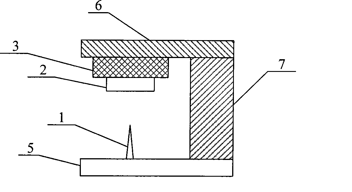
[0033] The positioner 4 in the above-mentioned embodiment 1 is composed of an XYZ positioning piezoelectric tube 7 and a probe seat 5 and a vibrator seat 6 respectively arranged at both ends thereof, as figure 2 , the vibrator 3 is fixed on the vibrator base 6, the probe 1 is fixed on the probe base 5 and points to the sample 2 fixed on the vibrator 3, so that the XYZ positioning piezoelectric tube 7 can complete the connection between the probe 1 and the sample 2 Positioning, scanning, and probe-sample gap adjustment. The variation of the force between probe 1 and sample 2 is given by the variation of the dynamic eigenfrequency of the vibrator.

Embodiment 3

[0034] Example 3: Using a quartz micro-fork vibrator to fix the probe and oscillate the sample without a micro-rod scanning force microscope mirror body.

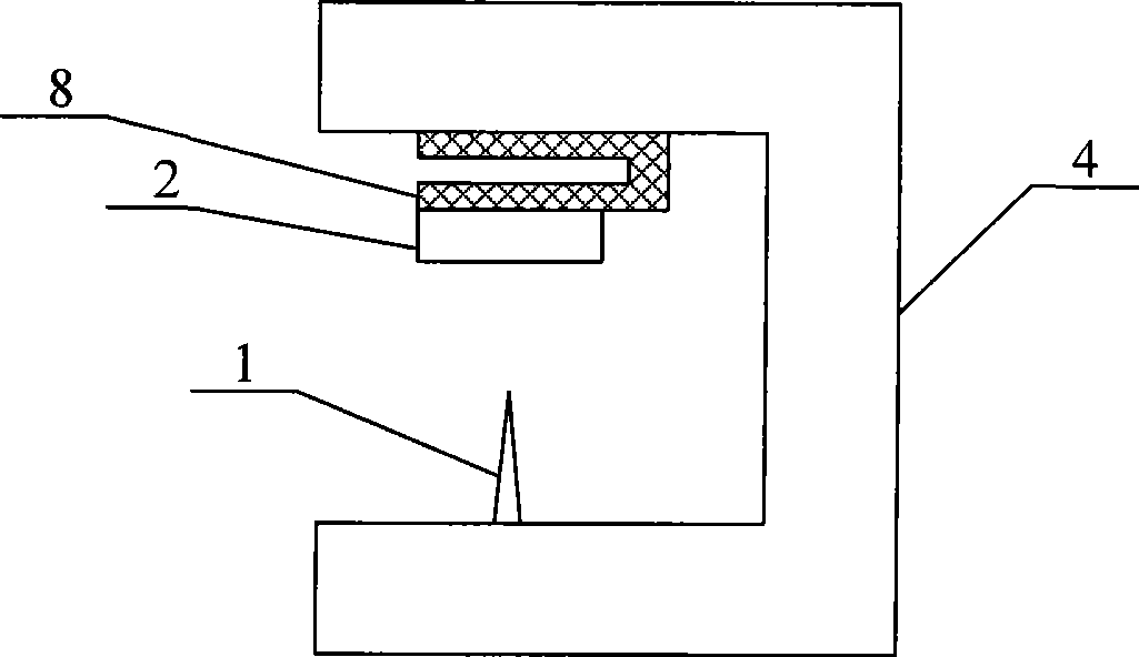
[0035] The vibrator 3 in the above embodiment may be a piezoelectric vibrator, preferably a crystal vibrator, especially a quartz vibrator. The quartz vibrator can also be in the shape of a plate or a tuning fork. image 3 It is a schematic diagram of the structure of the scanning force microscope mirror body of the microrod-free scanning force microscope using the quartz micro-fork vibrator 8 with the probe fixed and the sample oscillating.


PUM


Abstract

The invention relates to a non-microbot scanning force microscope body of a fixed probe and oscillated sample type, in particular to a scanning probe microscope which comprises a probe, a sample, a vibrator and a localizer, wherein the localizer is arranged between the probe and the vibrator, and the probe points to the sample fixed on the vibrator; the localizer comprises an XYZ positioning piezoelectric tube, a probe seat and a vibrator seat, the probe seat and the vibrator seat are respectively arranged at both ends of the XYZ positioning piezoelectric tube, and the probe and the vibrator are respectively fixed on the probe seat and the vibrator seat; the probe is a discrete non-microbot probe, and the vibrator is a piezoelectric vibrator, a crystal vibrator, a quartz crystal vibrator or a quartz micro fork. The invention has the advantages that the discrete non-microbot probe, such as an STM (Scanning Tunneling Microscope) probe, can be used, the cost of the probe is greatly decreased for benefiting the occurrence and the popularization of a microscope with better scanning force, the use of the crystal vibrator with high-quality factors can improve the frequency resolution and the measurement accuracy, and the addition of an auxiliary vibrator between the localizer and the vibrator can also obtain small-amplitude vibration so as to improve the measurement sensitivity of short range force and the atom resolution.

Description

technical field [0001] The invention relates to a scanning probe microscope, in particular to a scanning force microscope lens body with a probe fixed and a sample oscillating. Background technique [0002] Existing scanning force microscope (scanning force microscope, referred to as SFM), including atomic force microscope and magnetic force microscope, etc., its tip (tip) is fixed on one end of the probe microrod (cantilever), and along with the probe microrod Oscillating and oscillating, the sample is not oscillating. The change in the force between the probe and the sample is given by the change in the oscillation frequency of the probe microrod. This leads to four major difficulties: (1) The integration of probes and probe microrods is very difficult, usually using microfabrication and photolithography techniques, resulting in unbearably high costs. For example, the price of a piezo-resistive probe is as high as RMB 800 per piece. This makes SFM powerful enough to hav...

Claims


Application Information

Patent Timeline
IPC IPC(8): G01N13/16G01N13/22G12B21/22G01Q60/00
Inventor 陆轻铀侯玉斌吴飞
Owner UNIV OF SCI & TECH OF CHINA
Why Eureka
Try Eureka