
Automatic control device for greenhouse hot-water heating

An automatic control device, a technology for hot water heating, applied in digital control, electrical program control, household heating and other directions, can solve the problems of large power consumption, uneven indoor temperature field, high equipment requirements, and achieve uniform indoor temperature field. , The effect of reducing labor input and low energy consumption

Inactive Publication Date: 2009-05-13
KUNMING UNIV OF SCI & TECH
View PDF0 Cites 7 Cited by
  • Summary
  • Abstract
  • Description
  • Claims
  • Application Information

AI Technical Summary

Problems solved by technology

The hot air heating system uses the principle of heating the air. Compared with the hot water heating, the indoor temperature field is uneven, and it is easy to cause condensation on the leaves of the plants; Heating heating method, but due to the large power consumption, it is only suitable for air heating in greenhouses such as seedlings and experiments; radiant heating uses the release of infrared rays to directly heat the air, soil and plants in the greenhouse. The heating principle is through light energy It is converted into heat energy to increase the surface temperature, and then increase the temperature of the object and the surrounding air through convection and heat conduction, but the requirements for the equipment are high, the requirements for the reflector and its material properties are high, and the radiation loss to the side wall of the greenhouse is large; hot water heating The temperature inside the greenhouse is heated by heat dissipation in the radiator, so hot water heating systems are more suitable for large greenhouses
However, the temperature control of traditional hot water heating is to read the readings of the hanging thermometer in the greenhouse, judge the temperature, and use the switch of the boiler and valve to adjust the temperature in the greenhouse, which requires a lot of labor.

Method used


Image

  • Automatic control device for greenhouse hot-water heating
  • Automatic control device for greenhouse hot-water heating
  • Automatic control device for greenhouse hot-water heating

Examples


Embodiment Construction

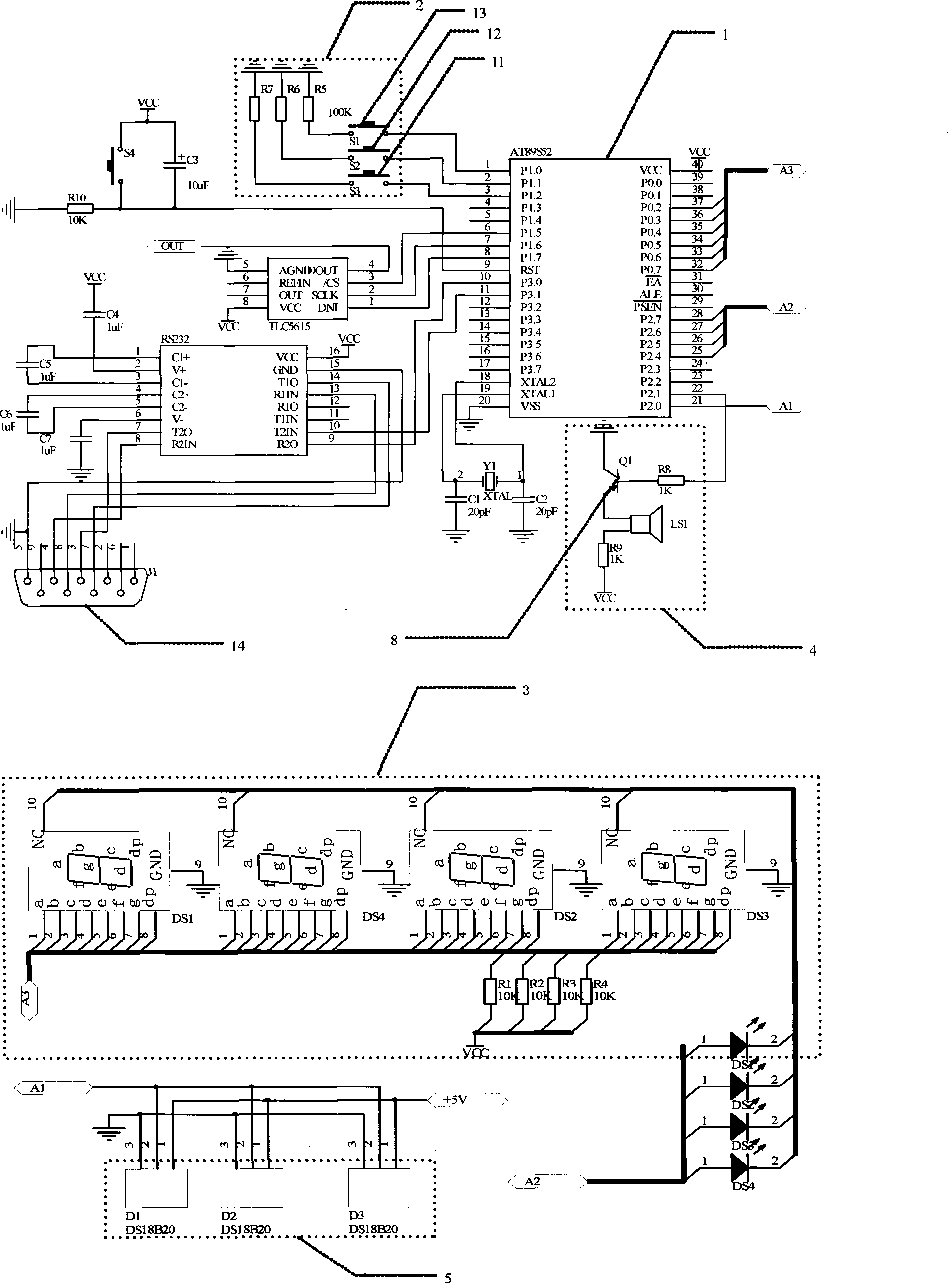
[0016] figure 1 The circuit shown includes three digital temperature sensors D1, D2, D3. Its SDATA end is connected with the P2.0 port of the single-chip microcomputer (CPU), the VCC end is connected with the power supply, and the GND end is grounded.

[0017] The circuit includes a display unit composed of a display digital tube 3, each field position control port of which is connected with the P0 port of the single chip microcomputer 1.

[0018] The circuit includes a customized keyboard 2, and the keyboard 2 is provided with three buttons 11, 12, 13, and each port is connected to the P1.0, P1.1, and P1.2 ports of the single-chip microcomputer 1 respectively.

[0019] The circuit includes a TLC5615 digital-to-analog conversion unit, whose DIN, CLK, and CS are respectively connected to the P1.7, P1.6, and P1.5 ports of the microcontroller 1, and the DOUT end is connected to the output data line to the electric regulating valve actuator.

[0020] The circuit includes an audi...


PUM


Abstract

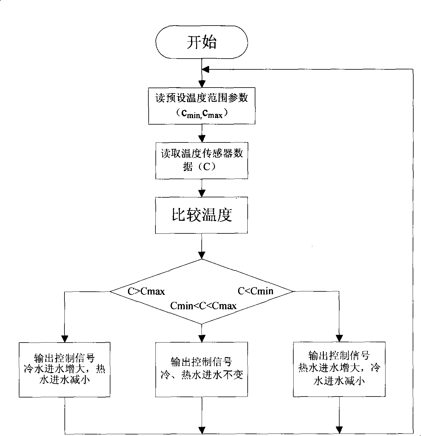
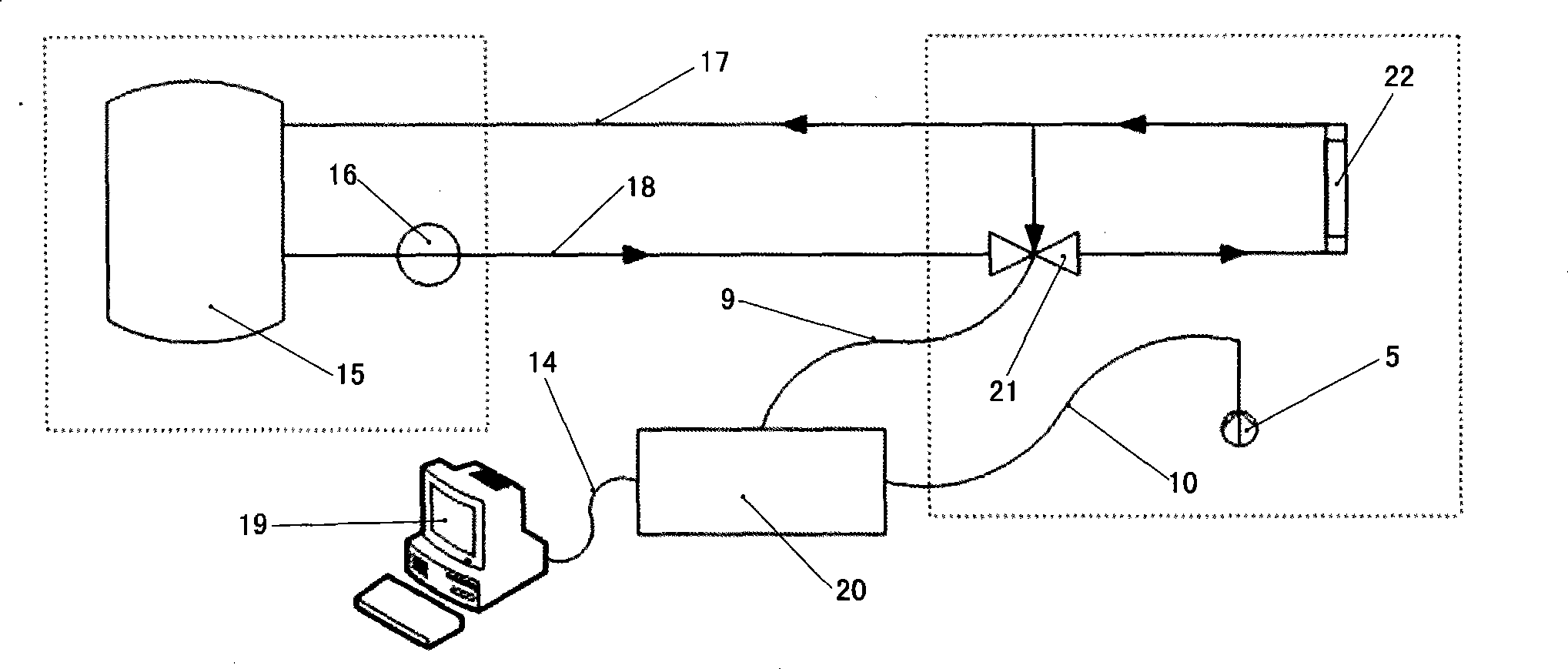
The invention provides an automatic hot water heating control device used in a greenhouse, and relates to the automatic hot water heating control device suitable for greenhouse heating. A single-chip microprocessor of a control system controller is electrically connected with a computer, an electric actuator which is connected with a regulating valve and a temperature sensor respectively by data lines, and the controller is internally provided with the single-chip microprocessor, an input keyboard and a display nixie tube. The temperature sensor measures the actual temperature in the greenhouse, the single-chip microcomputer periodically performs data acquisition, program storage, data processing and storage, setting information is input through the keyboard, the data are transmitted and stored in a host computer, a dedicated nixie tube display element displays the preset temperature and the measured temperature, finally, the single-chip microprocessor compares parameters, thus determining actuation direction and actuation time of the electric actuator, regulating the flow of the hot water in the a radiating tube, and automatically regulating the temperature in the greenhouse.

Description

technical field [0001] The invention relates to a heat supply control device, in particular to a hot water heating automatic control device suitable for greenhouse heat supply. Background technique [0002] At present, the commonly used heating methods in greenhouses are hot air heating, electric heating, radiant heating and hot water heating. The hot air heating system uses the principle of heating the air. Compared with the hot water heating, the indoor temperature field is uneven, and it is easy to cause condensation on the leaves of the plants; Heating heating method, but due to the large power consumption, it is only suitable for air heating in greenhouses such as seedlings and experiments; radiant heating uses the release of infrared rays to directly heat the air, soil and plants in the greenhouse. The heating principle is through light energy It is converted into heat energy to increase the surface temperature, and then increase the temperature of the object and the ...

Claims


Application Information

Patent Timeline
Patent Type & Authority Applications(China)
IPC IPC(8): F24D19/10G05B19/18
Inventor 罗小林闫聪李杰
Owner KUNMING UNIV OF SCI & TECH
Learn More