Bearing state diagnostic apparatus

A state diagnosis and bearing technology, which is applied in bearing assembly, bearings, measuring devices, etc., can solve the problems of high sensor price, lower S/N ratio, increased assembly man-hours, etc., to reduce the number of sensors, reduce temperature rise, and diagnostic accuracy Improved effect

Inactive Publication Date: 2009-05-13
OKUMA CORP
View PDF3 Cites 15 Cited by
  • Summary
  • Abstract
  • Description
  • Claims
  • Application Information

AI Technical Summary

Problems solved by technology

In this case, compared with a machine of the same structure that does not incorporate a sensor when the machine is assembled, it is necessary to perform wiring processing and sensor fixing, which generally increases the number of assembly man-hours. In addition, when the sensor fails and needs to be replaced , there is the possibility that more time must be spent
Moreover, since it is necessary to select a smaller sensor according to the size and structure of the machine, there may be problems such as high sensor price, unsatisfactory performance, and few types of options.
In addition, when the machine is composed of a plurality of bearings, the same number of sensors as the number of bearings is required, so there are problems such as high device cost and complicated components of the device and machine.
However, if the installation position of the sensor is separated from the vicinity of the bearing, for example, by assembling the outer circumference and end surface of the housing, the replacement of the sensor and the simplification of the components can be realized, but the S / N ratio is lowered.
In this case, of course, it is difficult to install a sensor on each bearing, and it becomes a structure in which one sensor diagnoses multiple bearings. Similarly, if a machine is composed of multiple bearings with similar specifications, there may be difficulties. Judging which bearing has a problem, etc.
[0006] In JP-A-2005-164314, even if it is a device that uses a sensor that can detect sound to diagnose the state of the bearing, since the change in the pressure transmitted in the air is measured, if the position of the sensor is far away from the For bearings, there is a possibility that the S / N ratio may decrease due to the influence of the sound around the machine, the sound from other than the bearing, the air temperature around the machine, etc.

Method used


Image

  • Bearing state diagnostic apparatus
  • Bearing state diagnostic apparatus
  • Bearing state diagnostic apparatus

Examples


Embodiment approach 1

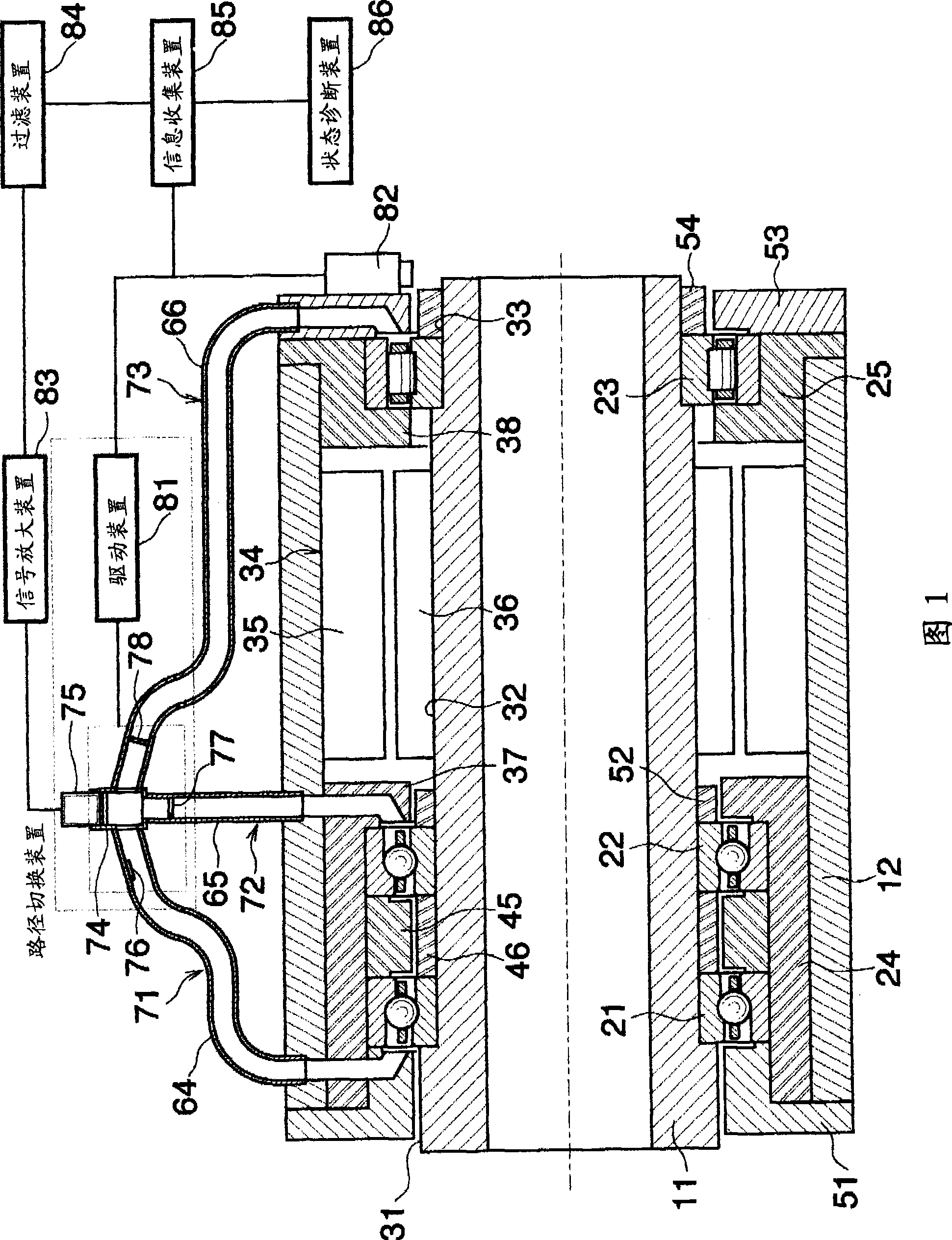
[0041] 1, the spindle device has a horizontal hollow shaft-shaped main shaft 11, a horizontal cylindrical sleeve 12 surrounding the main shaft 11, a first bearing 21 and a second bearing 22 on the left side of the main shaft 11 that are spaced apart in the axial direction. , the third bearing 23 supporting the right side of the main shaft 11, surrounding the first bearing 21 and the second bearing 22, and fixing the left housing 24 on the inner surface of the sleeve 12, surrounding the third bearing 23, and fixing on the inner surface of the sleeve 12 on the right side housing 25.

[0042] On the outer surface of the main shaft 11, there are provided a large-diameter portion 31, a middle-diameter portion 32, and a small-diameter portion 33 which are successively connected via steps from left to right.

[0043] A stator 35 of a motor 34 is fixed on the inner surface of the sleeve 12 between the second bearing 22 and the third bearing 23 . Corresponding to the stator 35 , a rot...

Embodiment approach 2

[0065] In Embodiment 2 shown in FIG. 6 , the three first to third detection sound propagation paths 71 to 73 gathered in Embodiment 1 are re-branched into three paths, and sensors are respectively installed on the branched paths. . In Embodiment 2, parts corresponding to those in Embodiment 1 are denoted by the same reference numerals in FIG. 6 , and description thereof will be omitted.

[0066] Three fourth to sixth pipes 101 to 103 are connected to the manifold pipe 74 . The fourth to sixth acoustic sensors 111 to 113 and the fourth to sixth opening and closing operation valves 121 to 123 are provided on the respective pipes 101 to 103 . The signals of the acoustic sensors 111 to 113 are amplified for each sensor by the signal amplifier 83 .

[0067] The frequencies detectable by the acoustic sensors 111 to 113 may be different for each sensor or may be the same. In addition, it is also possible to use a microphone in a wide range whose detectable frequency is several Hz ...

Embodiment approach 3

[0071] Next, Embodiment 3 will be described with reference to FIG. 7 .

[0072] In the third embodiment, a reference signal of a specific frequency is propagated to the bearings 21 to 23 shown in the first embodiment. In the third embodiment, as in the case of the second embodiment, the parts corresponding to those in the first embodiment are given the same reference numerals in FIG. 7 , and descriptions thereof are omitted.

[0073] A branch pipe 131 is arranged in parallel with the manifold pipe 74 . There is a reference signal generating device 132 on the branch pipe 131 .

[0074] The reference signal generator 132 is operated by the reference signal control device 133 . The reference signal is determined by the specifications of the acoustic sensor 75 . For example, in the case of an acoustic sensor whose detectable frequency is near a specific frequency of 20 kHz or higher, use a device that generates a reference signal of the frequency, or use a detectable frequency ...


PUM


Abstract

Provided is a bearing state diagnostic apparatus in which a sound generated from a bearing (21-23) is detected by a sound sensor (75), a detected value of the sound sensor (75) is compared with data which was previously formed, thereby diagnosing a state of the bearing (21-23), wherein at least one sound sensor (75) is disposed at a position separated away from an outer surface of a cylindrical support body (12, 24, 25) in which at least one bearing (21-23) is accommodated, the corresponding bearing (21-23) and sound sensor (75) are in communication with each other through a detection sound propagation path (71-73).

Description

technical field [0001] The present invention relates to a bearing state diagnosis device that detects, for example, a sound generated by a rolling bearing that supports a main shaft of a machine tool, and diagnoses the state of the rolling bearing based on the detected detection value. Background technique [0002] Bearings are used in many mechanical rotating machines, etc. Among bearings, rolling bearings are generally composed of an inner ring, an outer ring, a plurality of rolling elements, and cages for holding the rolling elements at equal intervals. The inner ring rotates with the shaft, and the outer ring is assembled and fixed on the housing. The bearing is filled with lubricating oil or lubricating oil is supplied to the bearing. During the rotation of the main shaft, an oil film is formed between the inner ring and the outer ring and the rolling elements. [0003] Although there is no problem when the bearing rotates normally, there may be cases where the machine...

Claims


Application Information

Patent Timeline
Patent Type & Authority Applications(China)
IPC IPC(8): G01M13/04F16C41/00
CPCG01M13/045F16C19/527
Inventor 矢野原直充则久孝志安藤知治
Owner OKUMA CORP
Why Eureka
Try Eureka