Hot dip galvanizing annealing process and high temperature annealing furnace

An annealing process and an annealing furnace technology, applied in the field of metallurgy, can solve the problems of large secondary investment in equipment, cumbersome equipment, and large production and maintenance, and achieve the effects of energy-saving equipment investment, primary investment cost reduction, and equipment investment reduction

Inactive Publication Date: 2010-05-26
CHONGQING CISDI THERMAL & ENVIRONMENTAL ENG CO LTD
View PDF9 Cites 0 Cited by
  • Summary
  • Abstract
  • Description
  • Claims
  • Application Information

AI Technical Summary

Problems solved by technology

[0010] 1) The traditional hot-dip galvanizing process is to heat the strip steel to 680-730°C in the front non-oxidation heating furnace, and then complete the secondary temperature rise of the strip steel in the subsequent radiant tube or muffle furnace. The equipment is cumbersome and the investment is large
[0011] 2) The above-mentioned background technology is the traditional hot-dip galvanizing annealing process, which has been widely used in various galvanizing production lines, and the technology is mature; but for production lines with small bandwidth (bandwidth less than 500mm) to solve the problem of investment, most of them are in the soaking section With the traditional reheating muffle furnace, because the muffle furnace is affected by the local hot spots of high-temperature reheating, frequent temperature fluctuations will occur, and its life is often short, resulting in unstable operation of the production line; the secondary investment of equipment is large, and production maintenance large amount
[0012] 3) Limited by the length of the muffle furnace, the traditional annealing furnace will be divided into several separate heating furnaces according to the length of the muffle furnace, and limited by the heat recovery equipment, the exhaust gas temperature is high and the heat utilization rate is very low
[0013] 4) At present, the development of regenerative combustion technology has entered a very mature stage, but there is no precedent for a large number of regenerative combustion in the annealing furnace with protective atmosphere

Method used


Image

  • Hot dip galvanizing annealing process and high temperature annealing furnace
  • Hot dip galvanizing annealing process and high temperature annealing furnace
  • Hot dip galvanizing annealing process and high temperature annealing furnace

Examples


Embodiment Construction

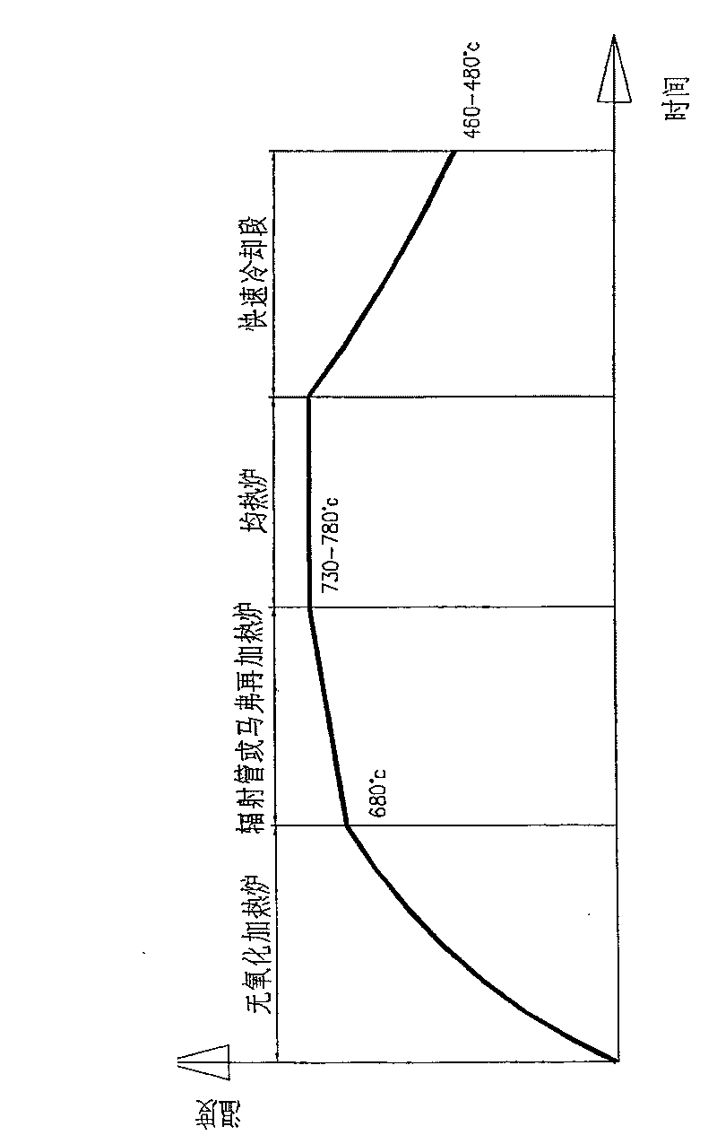
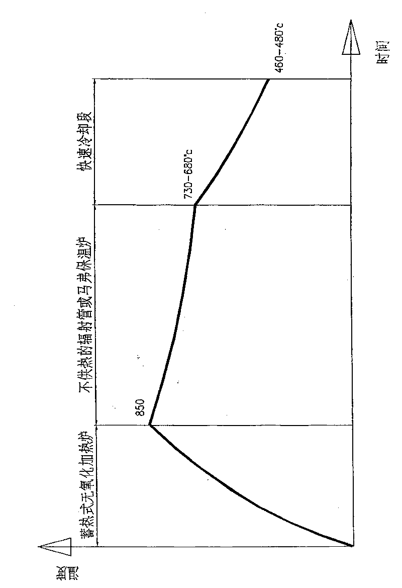
[0025] Attached below image 3 , 4 And 5 are further described to the specific embodiment of the present invention:

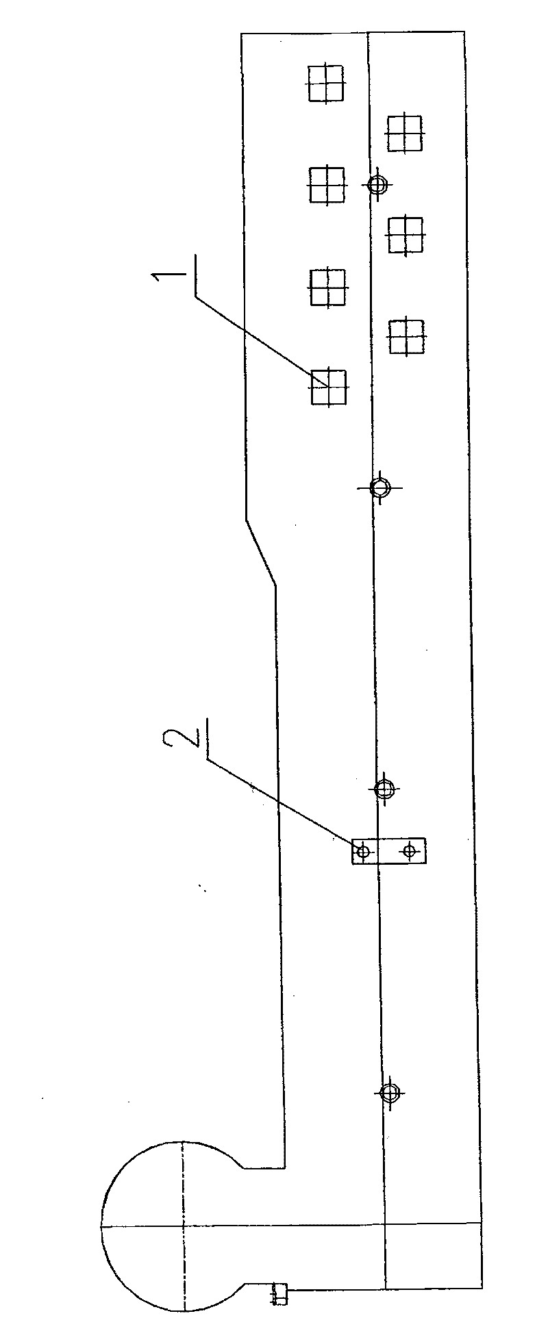
[0026] 1) The high-temperature annealing furnace includes a non-oxidizing regenerative heating furnace 10 , a non-heating holding furnace 8 and a rapid cooling section 9 .

[0027] Non-oxidation regenerative heating furnace 10: the heating furnace is provided with external combustion chambers 4a and 4b arranged in pairs, which are independent of the furnace hearth, and are arranged in pairs on both sides of the furnace hearth 6 respectively. The reversing valve 7 is externally connected to the devices 3a and 3b, and is controlled by the reversing valve 7, and turns into a heating combustion chamber and a heat storage combustion chamber; In the oxidative combustion mode, the combustion products enter the furnace in an incomplete combustion state after leaving the heating combustion chamber to heat the strip steel. The regenerators of the heating furnace inclu...


PUM


Abstract

The invention belongs to the technical field of metallurgy, and discloses a method for heat treatment, in particular a hot galvanizing annealing technique and a high temperature annealing furnace, which are adopted by galvanized wires. The method comprises the following steps: strip steel is heated in a non-oxidation regenerative heating furnace; the heated strip steel enters a heat holding furnace without supplying heat so as to lead the strip steel to complete reduction and recrystallization annealing; after the recrystallization annealing is completed, the strip steel enters a fast coolingsection and then enters a zinc pot by a steering roll chamber after being cooled. The high temperature annealing furnace used by the annealing technique comprises the non-oxidation regenerative heating furnace, the heat holding furnace without supplying heat and the fast cooling section. The invention can reduce the cost of one-time investment by more than 30 percent, simultaneously save the energy by more than 30 percent and can be widely applied to the hot galvanizing annealing technique of the galvanized wires.

Description

technical field [0001] The invention belongs to the technical field of metallurgy, and relates to a heat treatment method, in particular to a hot-dip galvanizing annealing process and a high-temperature annealing furnace adopted by a galvanizing line. Background technique [0002] In the traditional galvanizing process, there are various annealing processes, such as the well-known American Steel Union method with full radiant tube; the Selas method of directly heating the strip steel to the annealing temperature by using a non-oxidizing open flame; Modified Sendzimir method for removal of rolling emulsified oil prior to temperature change. [0003] The purpose of the Selas method is to directly heat the strip steel to the annealing temperature in a controlled-atmosphere non-oxidizing furnace, and then connect a short radiant tube soaking furnace, but the heating furnace and the soaking furnace need to be heated in sections. Enter the cooling section; achieve the purpose of ...

Claims


Application Information

Patent Timeline
Patent Type & Authority Patents(China)
IPC IPC(8): C21D9/56C21D1/26C23C2/28
Inventor 杨柏松
Owner CHONGQING CISDI THERMAL & ENVIRONMENTAL ENG CO LTD
Why Eureka
Try Eureka