An Alternate Fixture Type Metal Surface Treatment System

A metal surface treatment and surface heat treatment technology, applied in heat treatment furnaces, heat treatment equipment, heat treatment process control, etc., can solve the problems of decreased adhesion of paint particles, loose isolation butterfly valve closure, unqualified spraying process, etc., to achieve mechanical automation High efficiency, reduced energy consumption, and improved automation

Active Publication Date: 2020-09-29
苏州天金刚金属制品有限公司
View PDF9 Cites 0 Cited by
  • Summary
  • Abstract
  • Description
  • Claims
  • Application Information

AI Technical Summary

Problems solved by technology

Under the premise that the air pressure is basically unchanged, the main reasons for the paint falling off are as follows: 1. The spraying process is unqualified or the type of paint does not meet the requirements. The staff can be notified to deal with it by strengthening the spraying process or replacing the paint; 2. There is too much moisture in the air. As the temperature rises, the moisture will intensify the corrosion of the paint and cause it to fall off. There are two situations here, one The moisture content in the ambient air is already high, and activated carbon is usually added for drying at this time; the other is that in a heat treatment device equipped with a steam generator (generally used for surface oxidation of steel), the steam generator supplies steam The isolation butterfly valve of the pipe is not closed tightly, which causes the generator gas containing high moisture to be entrained when the air flows. At this time, it is necessary to isolate the relevant pipeline or manually tighten the isolation butterfly valve

Method used


Image

  • An Alternate Fixture Type Metal Surface Treatment System
  • An Alternate Fixture Type Metal Surface Treatment System
  • An Alternate Fixture Type Metal Surface Treatment System

Examples


Embodiment Construction

[0034] The present invention is further described in conjunction with the following examples.

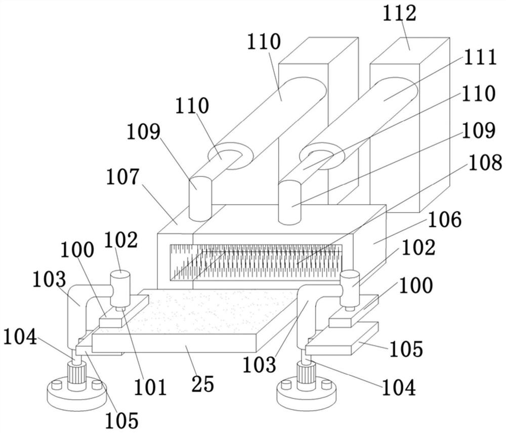
[0035] See eg figure 1 An alternate fixture type metal surface treatment system is shown, including a surface cleaning device and a surface heat treatment device. The metal plate 25 is cleaned by the surface cleaning device for surface dust removal, and then coated with paint, and then sent to the surface heat treatment device by the operator Carrying out surface heat treatment, the surface cleaning device includes splints 100 arranged on both sides of the metal plate 25, each splint 100 is affixed to a hydraulic cylinder output rod 101, and the hydraulic cylinder 102 is affixed to the motor output shaft 104 through an L-shaped rod 103, A pressure plate 105 is fixedly attached to the side wall of the L-shaped bar 103 . It also includes a main brush box 106 and a secondary brush box 107 with front openings. The upper and lower side walls of the main brush box 106 and the secondary b...


PUM


Abstract

The invention discloses an alternating clamp type metal surface treatment system. The alternating clamp type metal surface treatment system comprises a surface cleaning device and a surface heat treatment device; a metal plate is subjected to surface dust removing cleaning through the surface cleaning device, and then paint coating is performed; later, the metal plate is conveyed by an operator into the surface heat treatment device for surface heat treatment; the surface cleaning device comprises clamping plates correspondingly arranged on the two sides of the metal plate; each clamping plateis fixedly connected with one hydraulic cylinder output rod; a hydraulic cylinder is fixedly connected with a motor output shaft through an L-shaped rod; the side wall of the L-shaped rod is fixedlyconnected with an abutting pressing plate; a main brush box with an opening in the front end and an auxiliary brush box are further included; the upper and lower side walls of the main brush box and the auxiliary brush box are each fixedly connected with a plurality of flexible brush wires; the upper walls of the main brush box and the auxiliary brush box are fixedly connected with pneumatic cylinder output rods through connection columns; and pneumatic cylinders are fixedly connected to vertical plates.

Description

technical field [0001] The invention relates to the field of intelligent manufacturing and processing, in particular to an alternate fixture type metal surface treatment system. Background technique [0002] In metal surface treatment, for some metals that are not convenient to be directly exposed to the air at high temperature for heat treatment, it is generally necessary to clean the surface at room temperature first, then apply paint, and then perform heat treatment. The existing metal surface cleaning devices basically use splints to clamp first, and then use flexible brushes for automatic surface cleaning. The metal surface clamped by the splints needs to be manually cleaned separately, which is a waste of labor and is not conducive to automatic processing upgrades. . [0003] In metal surface heat treatment, air convection heating is a relatively common treatment method. For metals that are not easy to be directly exposed to the air at high temperature for heat treat...

Claims


Application Information

Patent Timeline
Patent Type & Authority Patents(China)
IPC IPC(8): C21D1/70C21D9/00C21D11/00C21D1/76
CPCC21D1/70C21D1/76C21D9/00C21D11/00Y02P10/20
Inventor 陈小辉其他发明人请求不公开姓名
Owner 苏州天金刚金属制品有限公司
Why Eureka
Try Eureka