Support connection device for warp beam of warping machine

A technology for supporting connecting devices and warping machines, applied in warping machines, other manufacturing equipment/tools, textiles and papermaking, etc., can solve problems such as yarn scrambling, surface unevenness, and affecting yarn unwinding quality, etc. Achieve the effects of improving quality, easy penetration, and energy saving

Inactive Publication Date: 2009-05-20
姜一
View PDF3 Cites 2 Cited by
  • Summary
  • Abstract
  • Description
  • Claims
  • Application Information

AI Technical Summary

Problems solved by technology

The yarn-feeding batch warping machine solves the problem of uniformity and controllability of the winding density well, and the problems of impermeable dyeing and shaft explosion no longer occur. Disturbance, resulting in uneven surface, which will affect the quality of yarn unwinding in severe cases

Method used


Image

  • Support connection device for warp beam of warping machine
  • Support connection device for warp beam of warping machine
  • Support connection device for warp beam of warping machine

Examples


Embodiment 1

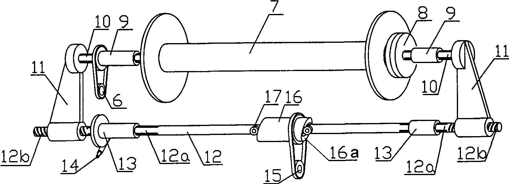
[0022] control figure 1 , the two spline shafts 10 are coaxially placed on the two ends of the warp shaft 7, the inner end of each spline shaft 10 is connected to the connecting disc 8, and the two connecting discs 8 are respectively pressed against the warp shaft 7. The corresponding end makes it connected with the warp beam 7 as a whole. The spline sleeve 9 is slipped on the spline shaft 10, and the winding transmission chain 6 made up of a belt and a pulley is connected to the outer peripheral side of the spline sleeve 9 on the right side. The warp shaft 7 and the spline shaft 10 rotate with the spline sleeve 9 .

[0023] The reciprocating shaft shift transmission mechanism 6 of this embodiment is mainly composed of a clapping arm 11, a clapping shaft 12, a spline sleeve 13, a cam 16, a roller 17, a clapping motor transmission chain 14 and an axial motor transmission chain 15. Clapping motor drive chain 14 is made up of worm gear reducer, belt and pulley, and axial motor ...

Embodiment 2

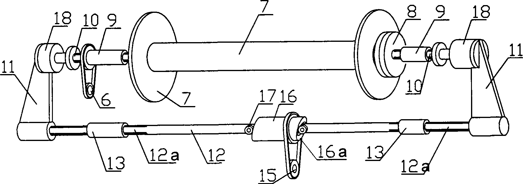
[0027] control figure 2 , the winding mechanism of this embodiment is the same as that of the above embodiment, and will not be repeated here. Its reciprocating shaft shift transmission mechanism is slightly different from the above-mentioned embodiment. It is mainly made up of clapping arm 11, clapping shaft 12, spline sleeve 13, cam 16, roller 17, cylinder 18 and axial motor drive chain 15. Axial motor transmission chain 15 is made up of belt and pulley. The two ends of clapping shaft 12 are provided with splines 12a, and two spline sleeves 13 are respectively slipped on the splines 12a. The linear and rotary motion of the snap-in shaft 12 is supported. The other ends of the two clapping arms are respectively connected to the rear seat of a cylinder, and the cylinder 18 is connected with the outer end of the corresponding spline shaft 10 by the thrust bearing installed at the top of the push rod thereon. When the cylinder works, the splined shaft 10 and the connecting d...

Embodiment 3

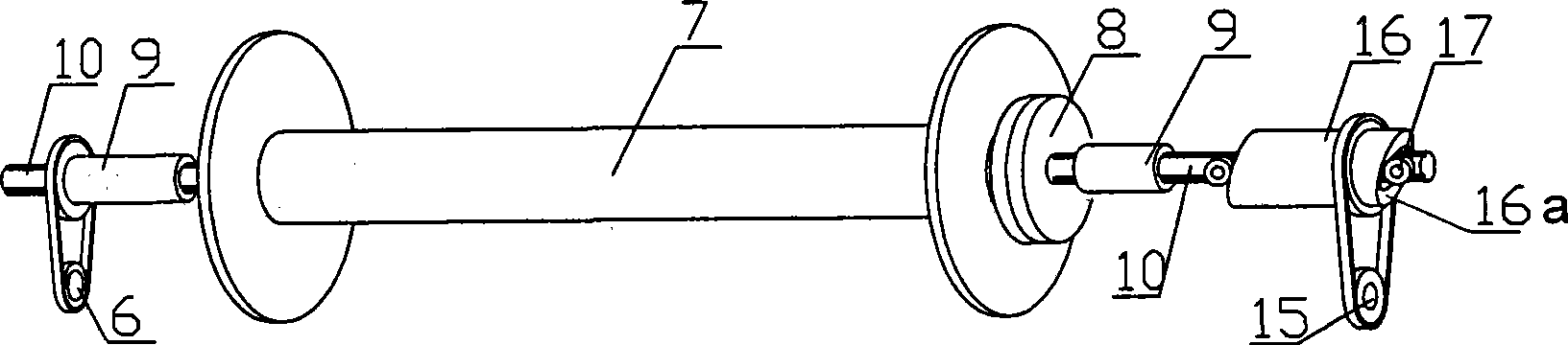
[0030] control image 3 , The winding mechanism part of the present embodiment is basically the same as that of Embodiment 1, except that the clapping or clapping of the two connecting discs 8 and the two ends of the warp beam 7 is done manually. When the two connecting discs 8 were connected or separated from the warp beam 7, the splined shaft 10 on the right side was fixed, and the splined shaft 10 on the left side could slide relative to the splined sleeve 9 on the left side, so that the connecting discs 8 and For the operation of clapping or clapping at the two ends of the warp beam 7, the connecting plate 8 and the warp beam 7 adopt bolts and nuts to clap and connect.

[0031] The corresponding reciprocating shaft shift transmission mechanism 6 is mainly composed of a cam 16 , a roller 17 and an axial motor transmission chain 15 . The cam 16 is sleeved on the spline shaft 10 in a cylindrical shape, and is coaxial with it. Equally, the two ends of cam 16 are provided wit...


PUM


Abstract

The invention relates to a warp beam supporting and connecting device of a warper, comprising a warp beam, a winding and driving chain for driving the warp beam, connecting discs, a spline housing, spline shafts and a reciprocating shaft moving and driving mechanism. The two spline shafts are arranged at two ends of the warp beam and have coaxial line with the warp beam, the inner side end of each spline shaft is connected with the connecting discs, the two connecting discs are respectively connected with the warp beam into a whole by tightly pressing on the corresponding end of the warp beam or a connecting piece, the spline housing is bushed on the spline shafts in a sliding way, the winding and driving chain is connected on the spline housing, and the reciprocating shaft moving and driving mechanism is connected with the outer side end of the spline shafts, and drives the warp beam to carry out axial reciprocating movement by the spline shafts. The warp beam supporting and connecting device has the advantages that: the warp beam can carry out axial reciprocating motion of small stroke simultaneously when winding to lead adjacent upper and lower layers of yarns to form cross winding, so as to solve the problem that dyeing liquor rushes the yarns to be disorderly often occurring in warp beam dyeing and improve the warp beam dyeing quality; and the yarns have good axial stability and can achieve smaller winding density, the dyeing liquor is easy to penetrate, and the pumping power of the dyeing liquor is reduced.

Description

technical field [0001] The invention relates to a textile machine, in particular to a support connection device for a warp beam of a warping machine. Background technique [0002] Dyeing yarns wound on warp beams is called warp beam dyeing. The dyed warp beams are then sized (simultaneously paralleled) and then wound into weaving beams, which become warp yarns for loom weaving. The warp beam dyeing method has many characteristics such as high efficiency, environmental protection and energy saving compared with the traditional method, and has been popularized and applied in recent years. [0003] The warp beam used for warp beam dyeing is different from general warp beams. It is made of stainless steel, and the garden cylinder of the shaft tube has dense small holes. When dyeing, multiple warp beams full of yarns are placed in a high-temperature and high-pressure dyeing pot, and a main pump circulates the dye solution, so that the dye solution penetrates evenly from the insi...

Claims


Application Information

Patent Timeline
Patent Type & Authority Applications(China)
IPC IPC(8): D02H13/00D02H13/28D02H3/00
Inventor 姜一
Owner 姜一
Why Eureka
Try Eureka