Non-barrier three-reflector optical system

A three-mirror, optical system technology, applied in the field of optical systems, achieves the effect of reducing free variables, increasing design difficulty, and increasing free variables

Inactive Publication Date: 2009-05-20
SUZHOU UNIV
View PDF0 Cites 27 Cited by
  • Summary
  • Abstract
  • Description
  • Claims
  • Application Information

AI Technical Summary

Problems solved by technology

[0022] However, it has not been reported that the freeform surface is applied to the optical system of the front objective lens of the spectral imager.

Method used


Image

  • Non-barrier three-reflector optical system
  • Non-barrier three-reflector optical system
  • Non-barrier three-reflector optical system

Examples


Embodiment 1

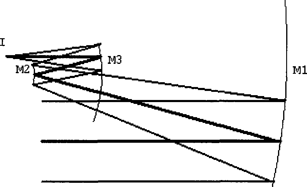
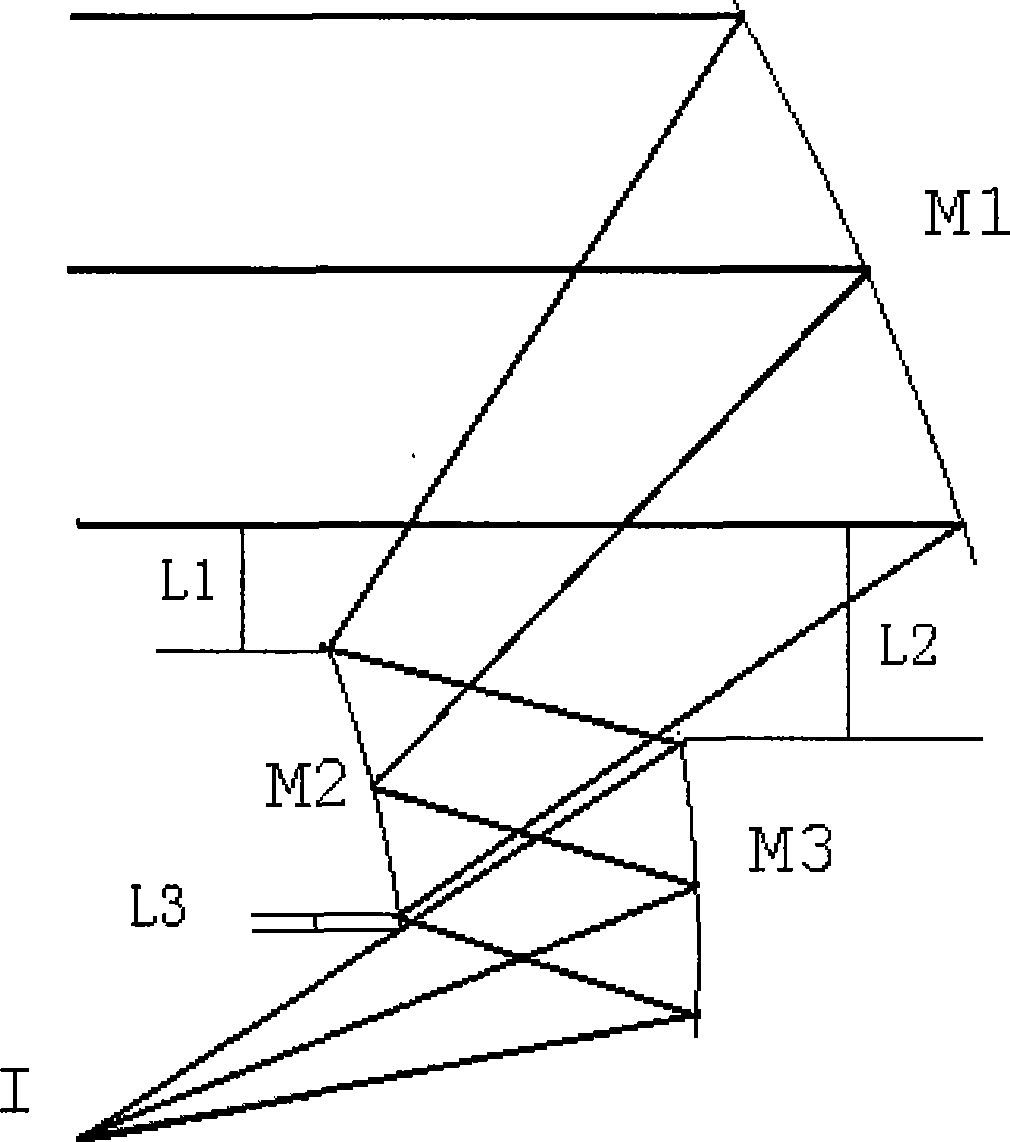
[0053] See attached figure 2 , which is a structural schematic diagram of the optical system of the present embodiment; wherein, M1 is the primary mirror, M2 is the secondary mirror, M3 is the third mirror, I is the image plane, and L1 is for avoiding obstruction, the lowermost edge light of M1 and the light of M2 The distance of the uppermost edge ray in the direction perpendicular to the optical axis, L2 is the distance between the lowermost edge ray of M1 and the uppermost edge ray of M3 in the direction perpendicular to the optical axis when avoiding occlusion, and L3 is the distance between the uppermost edge ray of M1 and M2 when avoiding occlusion The distance between the lower edge ray and the uppermost edge ray of M3 in the direction perpendicular to the optical axis.

[0054] The relative aperture D / f of the system is 1, the focal length is 360mm, and the field of view is 3°×0.02°. The system is off-axis to avoid obstruction; the optical path of the system is the t...

Embodiment 2

[0067] See attached Image 6 , which is a structural schematic diagram of the optical system of this embodiment; wherein M1 is the primary mirror, M2 is the secondary mirror, and M3 is the third mirror. The focal length is 360mm, the relative aperture of the system is 1 / 2.4, and the field of view is 3°×0.02°.

[0068] The aperture of the system is on the secondary mirror, the secondary mirror M2 is on the focal plane of the triple mirror M3, the image side is telecentric, the distance between the rear working distance image plane I and the secondary mirror M2 is 80mm, and the system structure size is about 280mm(z) ×240mm(y)×150mm(x). L1, L2, and L3 are 10mm, 10mm, and 10mm, respectively. Each mirror radius approximately satisfies the Petswan condition. The three mirrors are all Zernike free-form surfaces. The specific structural parameters and Zernike polynomial coefficients of the system are listed in Table 4 through the optimization design of the optical design software....

Embodiment 3

[0078] See attached Figure 10 , which is a structural schematic diagram of the optical system of this embodiment. Among them, M1 is the primary mirror, M2 is the secondary mirror, and M3 is the third mirror. The focal length is 360mm, the relative aperture D / f is 1 / 2.4, and the field of view is 3°×2°.

[0079] The secondary mirror M2 is on the focal plane of the three-mirror M3, the image side is telecentric, the rear working distance is 80mm from the image plane I to the secondary mirror M2, and the system structure size is about 800mm(z)×240mm(y)×150mm( x). L1, L2, L3 are 20mm, 30mm, 10mm respectively. The radius of each surface approximately satisfies the Petzwan condition. The three mirrors are all Zernike free-form surfaces, and the aperture is on the secondary mirror. The optical design software optimizes the design, and the specific structural parameters and Zernike polynomial coefficients of the system are listed in Table 6.

[0080] Table 6: System structure par...


PUM


Abstract

The invention discloses an unshielded three-reflector optical system, which can be used in a wide spectral imaging system with wave band from ultraviolet to infrared, and is particularly applicable to a preposed object lens of a spectrum imager. The system consists of a main reflector, a secondary reflector and a third reflector with aperture ratio of 1 / 0.5-1 / 3; the system avoids shielding through inclining elements; a beam path of the system is telecentric beam path in the image side; a principle ray of zero field coverage is spread along links of the vertex of each element; a diaphragm is arranged on the secondary reflector; the secondary reflector is arranged on a focal plane of the third reflector; focal power of the main reflector, the secondary reflector and the third reflector is positive, negative and positive respectively; curvature radiuses of the vertexes of the three reflectors approximately meet the condition of Petzval; and types of the three reflectors are Zernike free surfaces. The system has reasonable residual aberration distribution to greatly improve image quality, and can easily avoid shielding, so that the effective use area of each mirror face is equivalent to an original mirror; and the primary ray of the zero field coverage of the system moves along the links of the vertex of each surface, thereby facilitating the processing, assembly and regulation of the system.

Description

technical field [0001] The invention relates to an optical system, in particular to an unobstructed large relative aperture three-mirror optical system, which can be used in a wide-spectrum imaging system from ultraviolet to infrared, and is especially suitable for the front objective lens of a spectral imager, which belongs to the optical technology field. Background technique [0002] At present, in the field of optical system design, unobstructed three-mirror optical systems are generally designed using quadric surfaces or even-order aspheric surfaces. In the article "A Design of Front Objective Lens of Imaging Spectrometer" ([J]. Acta Photonica Sinica, 2003, 29(4): 498-499), an optical system is disclosed, see attached figure 1 , which is composed of primary mirror M1, secondary mirror M2 and third mirror M3. In this system, the size of the primary mirror is much larger than the effective use size. The image quality of the optical system with this surface design is not ...

Claims


Application Information

Patent Timeline
Patent Type & Authority Applications(China)
IPC IPC(8): G02B17/06G02B27/00
Inventor 沈为民宫广彪
Owner SUZHOU UNIV
Why Eureka
Try Eureka