Flotation cell without transmission

A flotation cell and cell technology, applied in flotation, solid separation, etc., can solve the problem of prolonging the induction time of high-energy micro-bubbles and fine particles, reducing the probability of collision between fine particles and bubbles and the probability of mineralization, flotation column Unable to produce a large number of uniform micro-bubbles, etc., to achieve the effect of concentrate filtration, high enrichment ratio and separation efficiency, and good mineralization effect

Active Publication Date: 2009-05-27
GUIZHOU BRANCH CHINA ALUMINUM IND
View PDF0 Cites 14 Cited by
  • Summary
  • Abstract
  • Description
  • Claims
  • Application Information

AI Technical Summary

Problems solved by technology

Moreover, under the effect of microbubble buoyancy, coarse particles cannot rise rapidly upward in a low turbulence state, nor can they quickly reach the foam layer and overflow into the foam tank, so the feature of "coarse particle flash floating" cannot be realized.
Moreover, since the air bubbles are mineralized in the column with a larger diameter, the dispersion of the gas in the column is uneven. Mineralization probability, thus prolonging the induction time of high-energy micro-bubbles and fine particles, reducing the attachment efficiency of fine particles and bubbles, making it impossible to achieve fine-grained high-energy micro-bubble flotation

Method used


Image

  • Flotation cell without transmission
  • Flotation cell without transmission
  • Flotation cell without transmission

Examples


Embodiment Construction

[0026] The present invention will be described in detail below in conjunction with the accompanying drawings and embodiments.

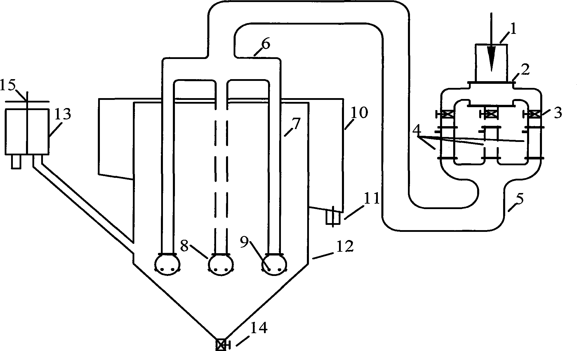
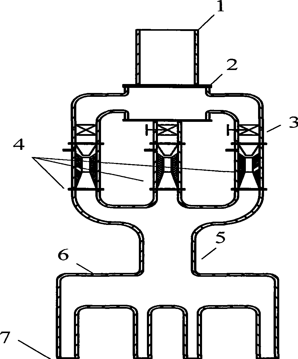
[0027] The driveless flotation cell of the present invention mainly includes a mineralization device and a spraying device, and the specific structure refers to the attached figure 1 :

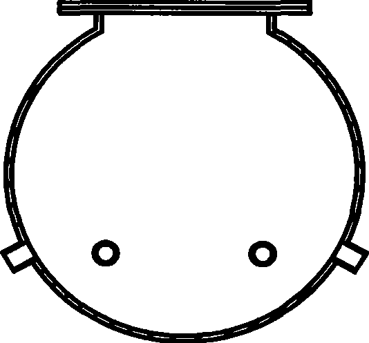
[0028] A feeding pipe 1 is arranged above the slurry distributor 2, and a group of Venturi tube groups 4 is arranged below, and a valve 3 is installed in each venturi tube of the Venturi tube group 4 . The bottom end of the Venturi tube group 4 is connected to the mineralization pipe 5, and the mineralization pipe 5 is connected to the pulp mixer 6, and a set of steel pipes 7 is arranged at the bottom end of the pulp mixer 6. The bottom end of the steel pipe 7 is provided with an ore slurry injection device 8 , and the ore slurry injection device 8 is provided with a nozzle 9 . The steel pipe 7 is installed in the tank body 12, the bottom of the tank body 12 is prov...


PUM


Abstract

The invention discloses a flotation cell without transmission, which comprises a cell body and a pulp distributer; wherein, a feeding pipe arranged above the pulp distributer, and at least one venturi pipe is arranged under the pulp distributer; the venturi pipe is connected with a mineralized pipe which is connected with the pulp distributer, the bottom end of which is provided with at least onepiece of steel pipe, and a pulp ejector device is arranged at the bottom end of the steel pipe and is provided with a plurality of nozzles; the steel pipe is installed in the cell body, and a foam collecting groove is installed at the upper part of the cell body; the cell body is connected with a middling ore box by a pipeline; the flotation cell has high separation efficiency and low energy consumption, can meet the requirements of aluminum-silicon separation process of alumyte flotation desiliconization with different fractions, and has wide application scope.

Description

technical field [0001] The present invention relates to a flotation device, in particular to a flotation cell, which belongs to the technical field of separation of granular materials. Background technique [0002] At present, there are many types of flotation equipment, mainly including flotation machines and flotation columns. The development of flotation machines has a history of many years at home and abroad, and the technology is becoming mature. But its inherent disadvantages are obvious, such as: high energy consumption, large footprint and so on. [0003] Flotation column is a kind of flotation equipment developed in this technical field in recent years, which is famous for its low energy consumption, small footprint and relatively simple structure. In order to ensure the sufficient mineralization of air bubbles and a series of separation processes to be fully and effectively carried out, the height of the flotation column is generally 7 to 8 meters, and some are e...

Claims


Application Information

Patent Timeline
Patent Type & Authority Applications(China)
IPC IPC(8): B03D1/14
Inventor 李旺兴陈湘清樊大林周杰强陈占华马俊伟陈兴华张建强吴拓宇余锋涛胡秋云
Owner GUIZHOU BRANCH CHINA ALUMINUM IND
Why Eureka
Try Eureka