Zig air flue K-shaped flow equalizing apparatus with flyash separation

A fly ash separation and flue technology, which is applied in lighting and heating equipment, etc., can solve the problems of catalyst wear, uniformity of the velocity distribution of difficult flue gas, and active passivation, and achieve the effect of uniform distribution.

Inactive Publication Date: 2009-05-27
XIAN THERMAL POWER RES INST CO LTD
View PDF0 Cites 5 Cited by
  • Summary
  • Abstract
  • Description
  • Claims
  • Application Information

AI Technical Summary

Problems solved by technology

The current equalization devices designed by professional environmental protection companies in the world basically adopt the methods of diversion cascades and abrupt cross sections. This method is not ideal for solving the above three problems, and there are mainly three shortcomings: 1) flying The ash is difficult to be separated from the flue gas, and will continue to enter the downstream equipment with the flue gas. This situation has an adverse effect on the operation of the catalyst in the denitrification reactor, which can lead to catalyst wear, activation passivation, and flow channel blockage 2) The deviation of the velocity distribution of the flue gas after turning is very large, and there is even a recirculation zone under certain operating conditions, which makes it difficult to meet the uniformity of the flue gas velocity distribution required by the denitrification and ammonia injection device; 3) The traditional flue gas The deviation of flue gas velocity distribution after the gas steering device is greatly affected by the unit load (flue gas volume), that is, the stability of the flow field is poor
The change of unit load leads to the change of flue gas velocity distribution, which is very unfavorable to the adjustment of downstream ammonia injection device

Method used


Image

  • Zig air flue K-shaped flow equalizing apparatus with flyash separation
  • Zig air flue K-shaped flow equalizing apparatus with flyash separation
  • Zig air flue K-shaped flow equalizing apparatus with flyash separation

Examples


Embodiment Construction

[0014] The present invention will be described in further detail below in conjunction with the accompanying drawings.

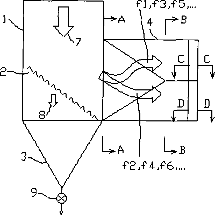
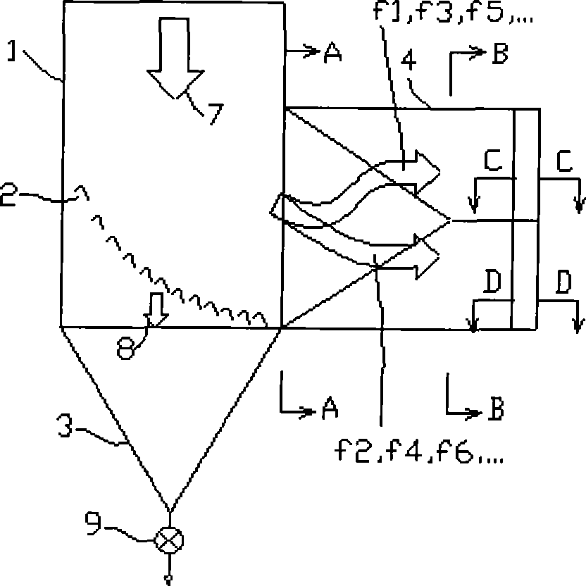
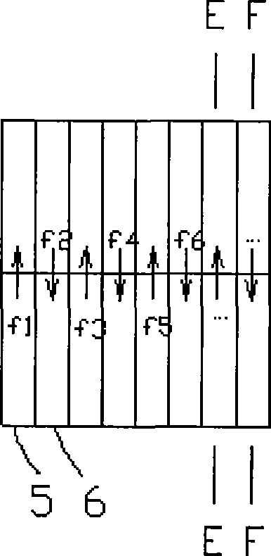
[0015] see Figure 1a , Figure 1b , 1 is the vertical flue, 2 is the delta-wing grille, 3 is the ash collecting hopper, 4 is the horizontal flue, 7 is the flue gas flowing vertically downward, 8 is the flue gas that enters the collector through the delta-wing grille 2 under the action of inertia The fly ash in the ash hopper 3, 9 is the ash discharge device, f1, f3, f5, ... are respectively the flake flue gas flow led to the upper half section of the horizontal flue through the upward small flue, f2, f4, f6, ... .Respectively, the sheet flue gas flow led to the lower half section of the horizontal flue through the small downward flue. The flue gas from the economizer is connected with the vertical flue 1 and the horizontal flue 4, and the lower end of the vertical flue 1 is provided with an ash collecting hopper 3 and an ash discharge device 9, and the vert...


PUM


Abstract

A K-type flow equalizing device with flying ash separated flashback air flue comprises a vertical air flue and a horizontal air flue, the lower end of the vertical air flue is provided with a flue-dust retainer and ash discharge device, the position of the vertical air flue turning to the horizontal air flue is provided with a flue gas turning external coating surface composed of delta wing grilles, the adjacent clearance between two delta wing grilles is communicated with the flue-dust retainer, the entrance of the horizontal air flue is distributed transversely with ascending and descending small air flues, the sum of the entrance cross sections of the ascending and the descending small air flues is equal to section area of the horizontal air flue, the ascending and the descending small air flues are alternately arranged inside the horizontal air flue and respectively introduces 50 0.000000lue gas to the upper semi-cross section of the horizontal air flue and 50 0.000000lue gas to the lower semi-cross section of the horizontal air flue. The flying ash described by the present invention is separated into the flue-dust retainer by delta wing grilles, which avoids the flue gas master stream from entering the flue-dust retainer and the flying ash from entering the flue gas by secondary entrainment, the ascending and descending small air flue alternate settings is alternately arranged in the horizontal air flue, the present invention realizes to make the severe oblique flow field distribution after acute steering in ultrashort distance evenly distribute in the whole air flue cross section rapidly.

Description

technical field [0001] The invention relates to a key technology in the high-temperature and high-dust flue gas denitrification system of a coal-fired boiler, that is, a flow equalizing device upstream of the ammonia injection device of the flue gas denitrification system from a vertical downward flue to a horizontal flue, and specifically relates to a The invention relates to a K-type flow equalizing device for a sharp-turning flue with fly ash separation. Background technique [0002] When the flue gas from the boiler economizer enters the downstream high-temperature and high-dust flue gas denitrification system, it usually first undergoes a sharp turn, that is, from vertical downward to horizontal direction. This process requires the use of flow equalization technology to ensure that the flue gas flow field on the ammonia injection section of the ammonia injection device arranged immediately after it is uniform. Due to the narrow space here, the flue gas flow direction i...

Claims


Application Information

Patent Timeline
Patent Type & Authority Applications(China)
IPC IPC(8): F23J15/02
Inventor 王月明张波马建兰牛国平
Owner XIAN THERMAL POWER RES INST CO LTD
Why Eureka
Try Eureka