

Cooler with defrosting heater and article storing device
A technology for defrosting heaters and coolers, which is applied to household refrigeration devices, defrosting, coolers, etc., and can solve the problems of unsuitable storage and the inability to shorten the distance between the cooler 60 and the defrosting heater 64, etc. space, improving retractability and usability, and maintaining safety
- Summary
- Abstract
- Description
- Claims
- Application Information
AI Technical Summary
Problems solved by technology
Method used
Image


Examples
Embodiment approach 1
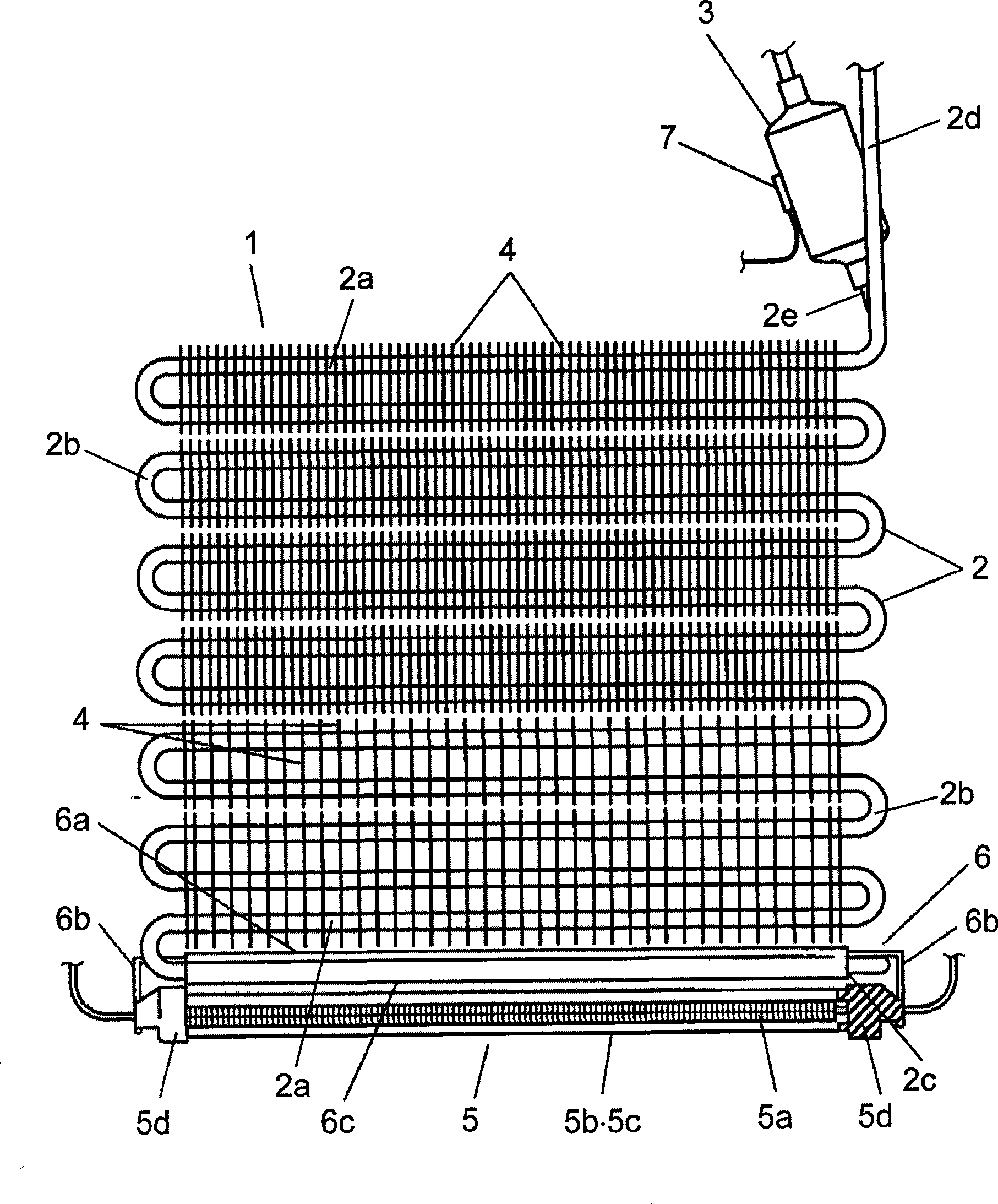
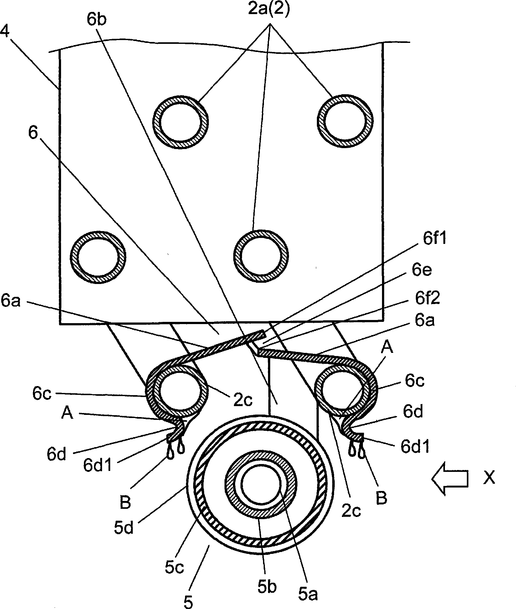
[0063] figure 1 It is a front view of the cooler with a defrosting heater according to Embodiment 1 of the present invention. figure 2 It is a side view of the cooler with a defrosting heater in the first embodiment. image 3 It is an enlarged side cross-sectional view of the defrosting heater peripheral portion of the cooler with the defrosting heater according to the first embodiment. Figure 4 It is an exploded perspective view of main parts showing the mounting structure of the defrosting heater of the cooler with the defrosting heater according to the first embodiment.
[0064] exist Figure 1 to Figure 4 Among them, the cooler 1 is mainly composed of a cooling pipe 2, a heat accumulator 3 and a fin 4, and the cooling pipe 2, the heat accumulator 3 and the fin 4 are respectively formed of aluminum material. The cooling pipe 2 is formed by bending an aluminum pipe in a meandering manner, and passes through a plurality of fins 4 . The cooling pipe 2 is alternately for...
Embodiment approach 2
[0100] Next, Embodiment 2 will be described. In addition, the same reference numerals are assigned to the same constituent elements as those in Embodiment 1, and detailed description thereof will be omitted.
[0101] Figure 5 It is an enlarged side cross-sectional view of a defrost heater peripheral portion of the cooler with a defrost heater according to Embodiment 2 of the present invention. Figure 6 It is an exploded perspective view of main parts showing the mounting structure of the defrosting heater of the cooler with the defrosting heater according to the second embodiment.
[0102] Figure 5 , Figure 6 The difference from Embodiment 1 is that the defrosting heater 5 transfers heat to and from the defrosting heater 5 by clamping the entire circumference of the cover 5d with the arc-shaped clamping portion 6H provided on the fixed portion 6B of the heat transfer plate 6. Fixing of plate 6.
[0103] With this structure, the defrosting heater 5 can be fixed on the ...
Embodiment approach 3
[0115] Next, Embodiment 3 will be described. In addition, the same reference numerals are assigned to the same constituent elements as those in Embodiments 1 and 2, and detailed description thereof will be omitted.
[0116] This embodiment differs from Embodiments 1 and 2 in that the heat transfer plate of this embodiment has not only the covering portion and the closely bonded portion, but also the heat receiving portion closely bonded to the defrosting heater.
[0117] Figure 7 It is a front view of the cooler with a defrosting heater according to Embodiment 3 of the present invention. Figure 8 It is a side view of the cooler with a defrosting heater in the third embodiment. Figure 9 It is an enlarged side cross-sectional view of a defrost heater peripheral portion of the cooler with a defrost heater according to the third embodiment. Figure 10It is a cross-sectional perspective view showing a main part of the defrosting heater attachment structure of the cooler with ...
PUM
 Abstract
Description
Claims
Application Information