
High-sensitivity atomic magnetometer

An atomic magnetometer, a high-sensitivity technology, applied in the direction of the size/direction of the magnetic field, can solve the problems of limited sensitivity and complicated devices, and achieve the effects of high sensitivity, simple devices, and intuitive and friendly interface

Inactive Publication Date: 2009-05-27
ZHEJIANG UNIV
View PDF0 Cites 36 Cited by
  • Summary
  • Abstract
  • Description
  • Claims
  • Application Information

AI Technical Summary

Problems solved by technology

[0003] In order to overcome the problems of complex and limited sensitivity of existing weak magnetic field measuring instruments, the present invention provides a novel high-sensitivity atomic magnetometer

Method used


Image

  • High-sensitivity atomic magnetometer
  • High-sensitivity atomic magnetometer
  • High-sensitivity atomic magnetometer

Examples


Embodiment 1

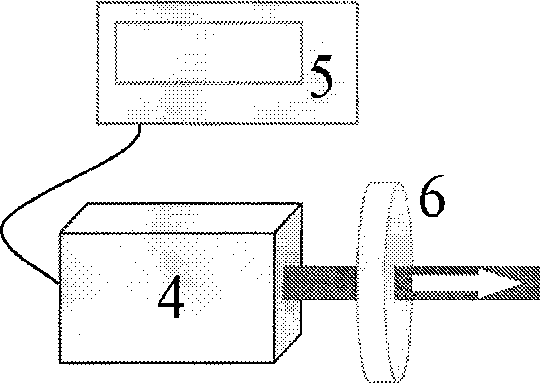
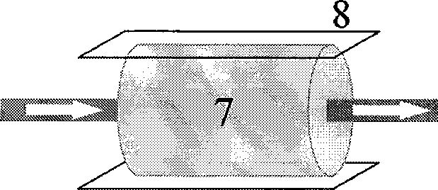
[0014] The overall structure of the high-sensitivity atomic magnetometer is shown in figure 1 , including a laser light source part 1, a weak magnetic field probe part 2 and a signal detection part 3, and the three parts are connected through a laser optical path to form a whole of a high-sensitivity atomic magnetometer. The structural diagram of the laser light source part 1 is shown in figure 2 , including a semiconductor laser 4, a laser control circuit 5 and a quarter-wave plate 6; the structural diagram of the weak magnetic field probe part 2 is as image 3 , including an alkali metal atomic bubble 7 and a modulation coil 8; the structural diagram of the signal detection part 3 is as follows Figure 4 , including photoelectric converter 9, lock-in amplifier 10 and data acquisition, processing equipment 11; Figure 5 is the computer program interface in the embodiment.

[0015] In the embodiment, rubidium-87 atoms are used as alkali metal atoms, and the size of the rub...


PUM


Abstract

A high-sensitivity atom magnetometer for measuring extremely weak magnetic field consists of laser source, a weak magnetic field probe and a signal detector; the three parts are connected by laser paths to form the integral of the high-sensitivity atom magnetometer. The high-sensitivity atom magnetometer, which can survey the weak magnetic field through measuring the variation of the intensity of the transmission laser which is caused by the combined function of laser, atomic air and weak field, has the advantages of high sensitivity, simple structure, friendly interface, low power consumption, etc.

Description

technical field [0001] The invention relates to a magnetic field measuring instrument, especially an instrument capable of measuring extremely weak magnetic fields. Background technique [0002] In modern technology, the detection of weak magnetic fields is a very important technology. The information of space magnetic field has very important applications, such as: space and near-surface detection, military technology, industrial detection, detection of human magnetic field, etc. At present, the weak magnetic field measuring instruments that are widely used mainly include proton precession magnetometer, optical pump magnetometer and low-temperature superconducting quantum interference magnetometer. Some of the above-mentioned magnetic field measurement techniques are not sensitive enough, and some devices are too complicated, thus limiting their scope of application. Contents of the invention [0003] In order to overcome the problems of complex devices and limited sens...

Claims


Application Information

Patent Timeline
Patent Type & Authority Applications(China)
IPC IPC(8): G01R33/02
Inventor 林强李曙光王兆英徐云飞
Owner ZHEJIANG UNIV
Learn More