DC parallel-serial transition electric power system

A technology of power supply system and DC power supply, which is applied to conversion equipment without intermediate conversion to AC, electric traction, electric vehicles, etc. The effect of series conversion, increasing cycle life and reducing damage

Active Publication Date: 2009-05-27
无锡德博尼新能源科技有限公司
View PDF0 Cites 16 Cited by
  • Summary
  • Abstract
  • Description
  • Claims
  • Application Information

AI Technical Summary

Problems solved by technology

[0002] At present, the known electric vehicle DC brushless motor controller is an electrical appliance that only accepts one power supply input, because the current power supply used on electric vehicles is a 24V, 36V or 48V DC power supply group composed of 12V batteries connected in series. , The service life of the 24V battery pack can be as long as 3 to 4 years, and the service life of the 36V battery pack can reach about 2 years. Difficult, very short mileage
Although the 48V battery pack can meet the requirements of electric vehicle starting, uphill, and continuation mileage, but because the number of single battery packs in series is too large, the probability of difference between the batteries in series increases, which results in The single battery with the smallest capacity is always over-discharged and under-charged, which makes the capacity of a single battery decay too quickly, and the capacity is often lower than 60% of the original capacity in less than a year.
The matching charger must also in...

Method used


Image

  • DC parallel-serial transition electric power system

Examples


Embodiment Construction

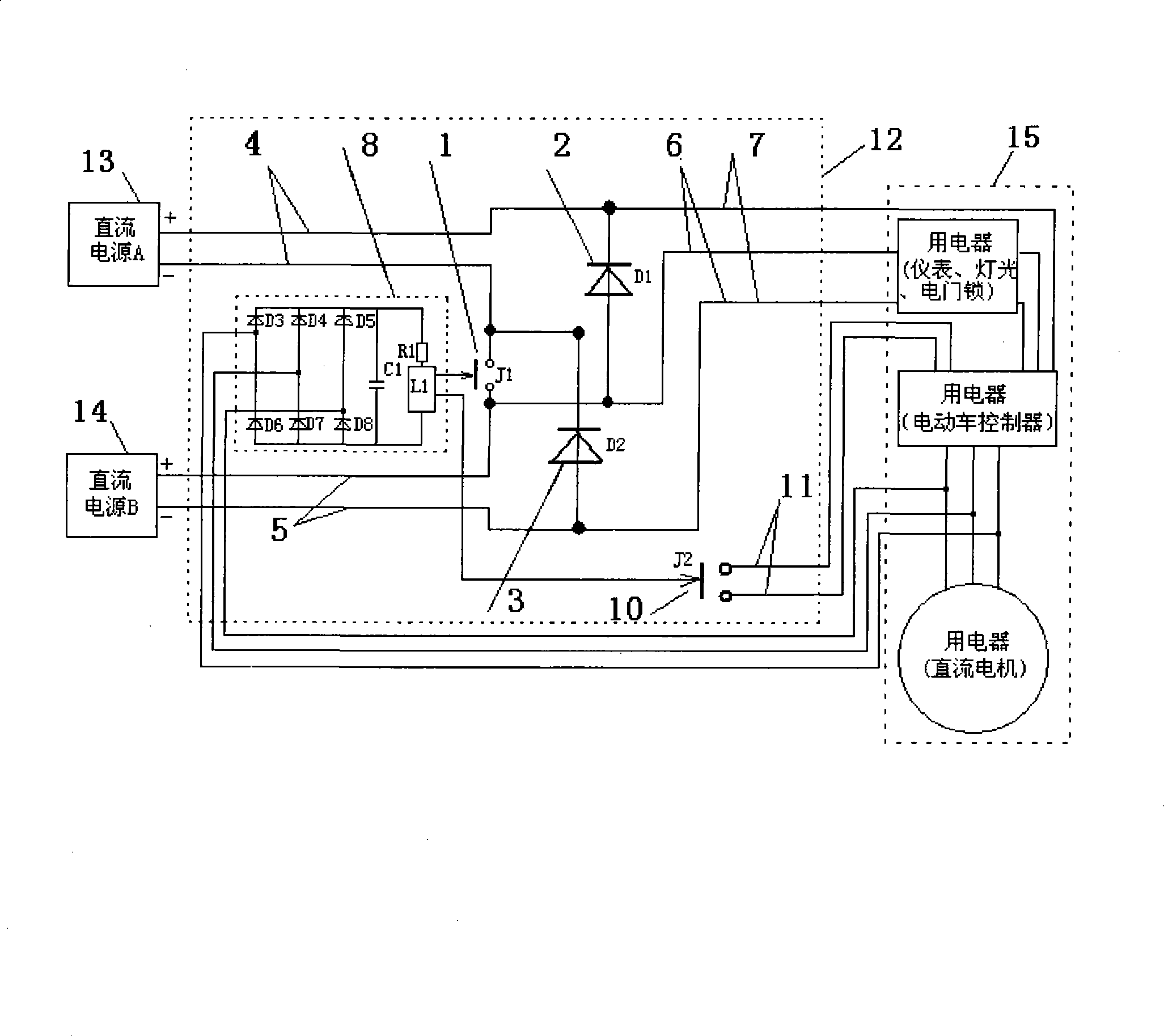
[0032] 1. Make a DC parallel converter 12: Make a DC parallel converter according to the DC parallel converter 12 shown in the figure, and the control switch circuit 8 is provided with 3 connecting wires to accept the feed from the phase line induction when the motor rotates, and Through the three-phase bridge rectification circuit, it is converted into direct current and connected to the logic device, and the logic device judges the motor speed and triggers switch 1 and switch 10 . The two contacts of the switch 1 are connected with the negative wire of the DC power connection 4 and the positive wire of the DC power connection 5 .

[0033] 2. Connection and installation: Connect the positive and negative wires of DC power supply A13 to DC power supply wiring 4 according to the figure, connect the positive and negative wires of DC power supply B14 to DC power supply wiring 5; connect the motor phase wire of electrical appliance 15 to control signal wire 9 The positive wire of ...


PUM


Abstract

The invention relates to the technical field of supplying electricity to a power utilization device after two groups of direct current power supplies are parallelly or serially connected, in particular to technology of supplying electricity to electric bicycles and electric automobiles, which comprises a direct current parallel-serial connection converter (12), wherein the direct current parallel-serial connection converter (12) is provided with a direct current power supply connection wire (4) and a direct current power supply connection wire (5) which can be connected with a direct current power supply (A13) and a direct current power supply B14, and is provided with a pair of positive and negative conducting wire direct current output connection wires (7) which are connected with a positive connection wire and a negative connection wire of the power utilization device. The technology has the advantages that the technology realizes the conversion of parallel-serial connection only by a switch, and solves common problems of conversion failure and battery short-circuit caused by non-synchronized switches when a plurality of switches realize the conversion of the parallel-serial connection, has a simple structure and reliable work, reduces the damage of heavy current to batteries through the normal parallel low-voltage output of the two groups of direct current power supplies and the serial high-voltage output when needing to be used, reduces the quantity of usable batteries in waste battery packs, reduces the count of rechargeable serial batteries, improves the discharging efficiency of the batteries, is favorable for the safety due to the adoption of high and low speed staged operation, and can meet different power supply demands at any time.

Description

technical field [0001] The invention relates to the technical field of connecting two sets of DC power supplies in parallel or in series to supply power to electrical appliances, in particular to the technology of supplying power to electric bicycles and electric vehicles. Background technique [0002] At present, the known electric vehicle DC brushless motor controller is an electrical appliance that only accepts one power supply input, because the current power supply used on electric vehicles is a 24V, 36V or 48V DC power supply group composed of 12V batteries connected in series. , The service life of the 24V battery pack can be as long as 3 to 4 years, and the service life of the 36V battery pack can reach about 2 years. Difficult and very short mileage. Although the 48V battery pack can meet the requirements of electric vehicle starting, uphill, and continuation mileage, but because the number of single battery packs in series is too large, the probability of differen...

Claims


Application Information

Patent Timeline
IPC IPC(8): H02M3/18B60L11/18B60R16/033
CPCY02T10/7005Y02T10/70
Inventor 王宏图
Owner 无锡德博尼新能源科技有限公司
Why Eureka
Try Eureka