Discharge device and air purifying device

A technology of air purification device and discharge device, applied in the direction of corona discharge device, spray discharge device, electrostatic spray device, etc., can solve the problem of difficulty in stabilizing the discharge state, and achieve the effects of improving processing performance, preventing sparks, and maintaining stable performance.

Inactive Publication Date: 2009-05-27
DAIKIN IND LTD
View PDF2 Cites 12 Cited by
  • Summary
  • Abstract
  • Description
  • Claims
  • Application Information

AI Technical Summary

Problems solved by technology

On the other hand, even with such detailed settings, if the distance between the electrodes changes due to the wear of the discharge electrodes due to discharge or foreign matter adheres to the discharge electrodes, sparks may not be generated, or glow light may be generated. Risk of weaker discharges such as glow corona discharges
As mentioned above, it is very difficult to stabilize the desired discharge state (especially streamer discharge) in existing discharge devices.

Method used


Image

  • Discharge device and air purifying device
  • Discharge device and air purifying device
  • Discharge device and air purifying device

Examples


no. 1 approach

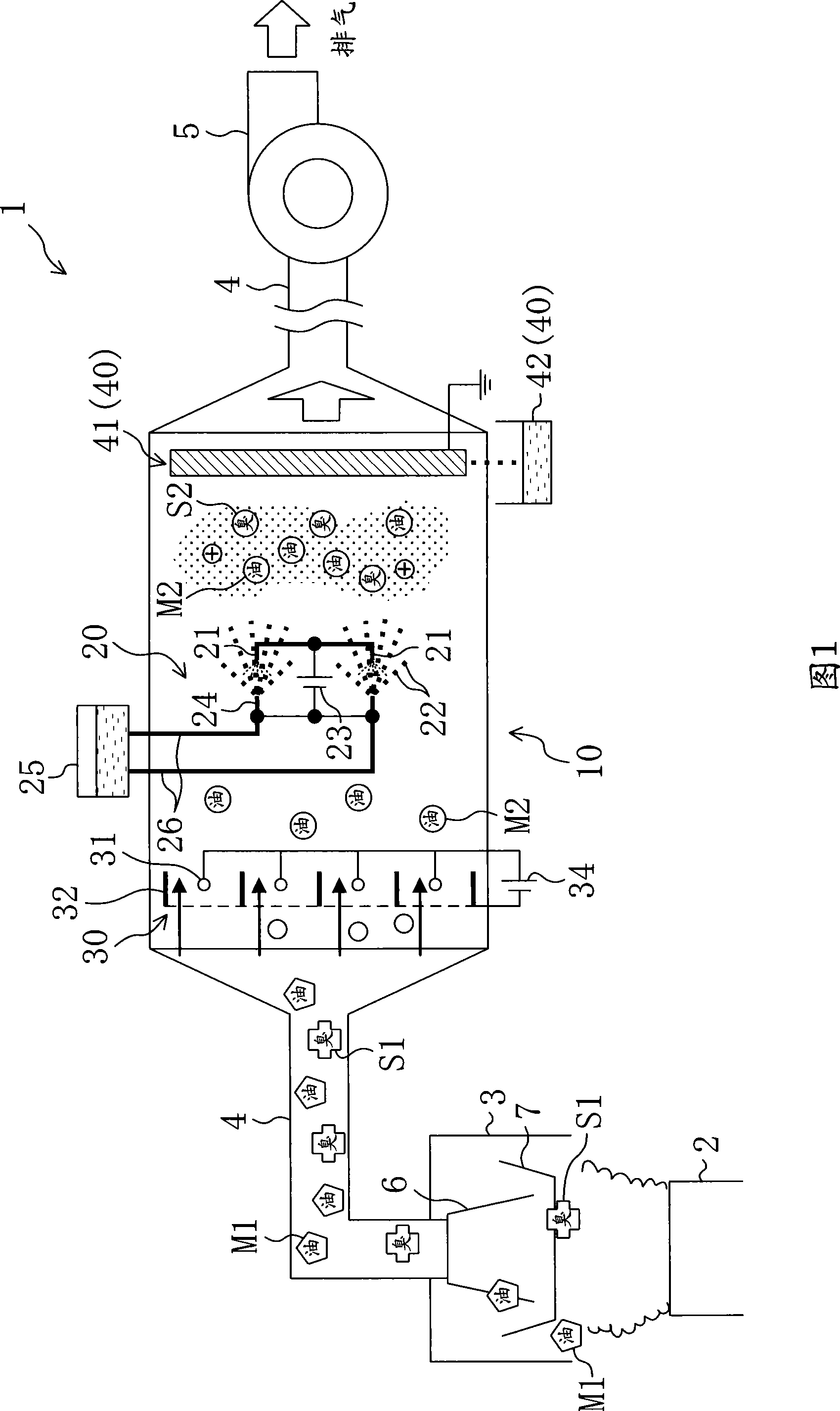
The first embodiment of the present invention is an example in which the air cleaning device 10 including the discharge device 20 according to the present invention is used as an exhaust duct for discharging exhaust gas from a kitchen of a restaurant to the outside, for example. FIG. 1 is a schematic diagram of a kitchen exhaust system 1 including the air cleaning device 10 .

[0067] As shown in this FIG. 1 , an exhaust hood 3 is provided above a cooking appliance 2 arranged in the kitchen. One end (indoor side end) of an exhaust duct 4 extending to the outside of the house is connected to the exhaust hood 3 , and an exhaust fan 5 is connected to the other end (outdoor side end) of the exhaust duct 4 . With this configuration, the air to be processed, that is, the kitchen exhaust, flows through the exhaust hood 3, the exhaust duct 4, and the exhaust fan 5 in sequence, and is released to the outside.

[0068] A grease filter 6 for capturing oil mist M1 and dust (not shown) con...

no. 2 approach

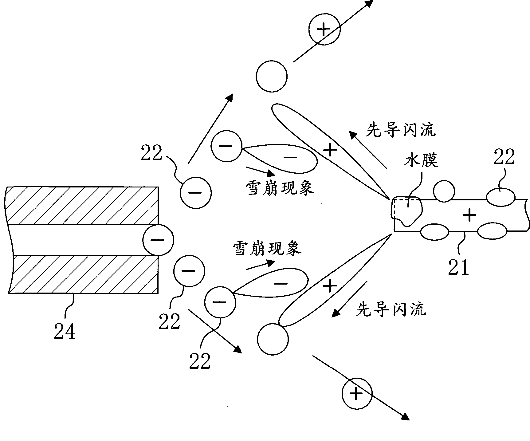
[0098] Under the situation of setting like this, because streamer discharge is carried out to liquid droplet 22, so still take place repeatedly following phenomenon, promptly: occur the avalanche phenomenon that the liquid droplet 22 that ejects from droplet ejector 24 takes place→from discharge electrode The pilot flash flow sent by 21 develops → the pilot flash flow disappears → the avalanche phenomenon of the droplet 22 appears →  …. Therefore, the discharge state is stable. When the discharge device 20 is used for the air cleaning device 10, the air cleaning performance improves.

[0099] —Modification of the second embodiment—

no. 3 approach

The third embodiment of the present invention is an example in which an air cleaner including the discharge device 20 according to the present invention is used in the household air cleaner 10 . The air cleaner 10 purifies the room by removing odorous components, harmful components, dust, and the like in the indoor air.

[0101] Such as Figure 9 As shown, the air cleaner 10 includes a rectangular housing 50 . An air intake port 51 is formed on the front surface of the casing 50 , and an air discharge port 52 is formed on the upper surface of the casing 50 . In the casing 50 , an air passage 53 through which indoor air as air to be processed flows is formed from the air intake port 51 to the air discharge port 52 .

[0102] In the air passage 53 , a dust collection filter 54 , streamer discharge unit 20 , catalyst treatment unit 55 , and blower fan 56 are provided in this order from the upstream side to the downstream side of the air passage 53 .

[0103] The dust collection...


PUM


Abstract

Disclosed is a discharge device comprising a particle ejector for emitting particles (a droplet ejector (24) for spraying droplets (22)). In this discharge device, the particles (droplets (22)) ejected from the particle ejector (droplet ejector (24)) toward a discharge electrode (21) are used as a counter electrode (22).

Description

technical field [0001] The invention relates to a discharge device for generating low-temperature plasma through discharge, and an air cleaning device for purifying air by using the low-temperature plasma generated by the discharge device. Background technique [0002] Conventionally, as the above-mentioned type of discharge device, there is a discharge device that generates streamer discharge from a needle-shaped discharge electrode to a planar counter electrode (for example, refer to Patent Document 1). In this device, low-temperature plasma is generated along with streamer discharge, and active species such as electrons and various excited molecules are generated. When the treated air flows through the low-temperature plasma, the odor components and harmful components contained in the treated air are decomposed by the active species and changed into carbon dioxide (CO 2 ) or water (H 2 O) without odorization. As a supplementary note, a catalyst is also provided in the ...

Claims


Application Information

Patent Timeline
Patent Type & Authority Applications(China)
IPC IPC(8): H01T19/00A61L9/18B01D53/38B05B5/025B05B5/08H05H1/24B01J19/08
CPCB03C2201/06B01D2255/2073B01D53/77B01D53/32H05H1/24B03C3/09B03C3/38B05B5/087B01D53/8678B03C3/16A61L9/22B01D2259/818B03C2201/10B03C3/12H05H1/48H05H1/471H05H2245/15A61L9/18
Inventor 茂木完治大堂维大田中利夫秋山龙司
Owner DAIKIN IND LTD
Why Eureka
Try Eureka