TDA dehydrating tower

A dehydration tower and tower body technology, which is applied in amino compound purification/separation, organic chemistry, fractionation, etc., and can solve problems such as plate efficiency drop, liquid flooding, and plate leakage

Inactive Publication Date: 2009-06-03
YANTAI JULI ISOCYANIC ESTER
View PDF0 Cites 5 Cited by
  • Summary
  • Abstract
  • Description
  • Claims
  • Application Information

AI Technical Summary

Problems solved by technology

At present, the method of dehydrating TDA in China adopts the rectification method of plate floating valve tower. There is a circular valve hole on the floating valve tower tray, and a valve plate that can float up and down in an appropriate range is installed in the hole. When working, the gas flows from The valve hole rises, opens the valve plate, passes through the annular gap, and then blows into the liquid layer in the horizontal direction to form foam to achieve the purpose of absorption. The float valve is the gas-liquid mass transfer element of the float valve tower. The float valve tower has the following disadvantages: 1) When the gas velocity is low, there is still liquid leakage from the tray, resulting in a decrease in the efficiency of the tray; 2) The valve plate of the float valve may be stuck and blown off, which will cause difficulties in operation and maintenance; 3) The pressure drop of the tray is large, which hinders the application under high gas phase load; 4) Liquid flooding is prone to occur in the rectification operation, and the anti-risk operability is poor

Method used


Image

  • TDA dehydrating tower
  • TDA dehydrating tower
  • TDA dehydrating tower

Examples


Embodiment 1

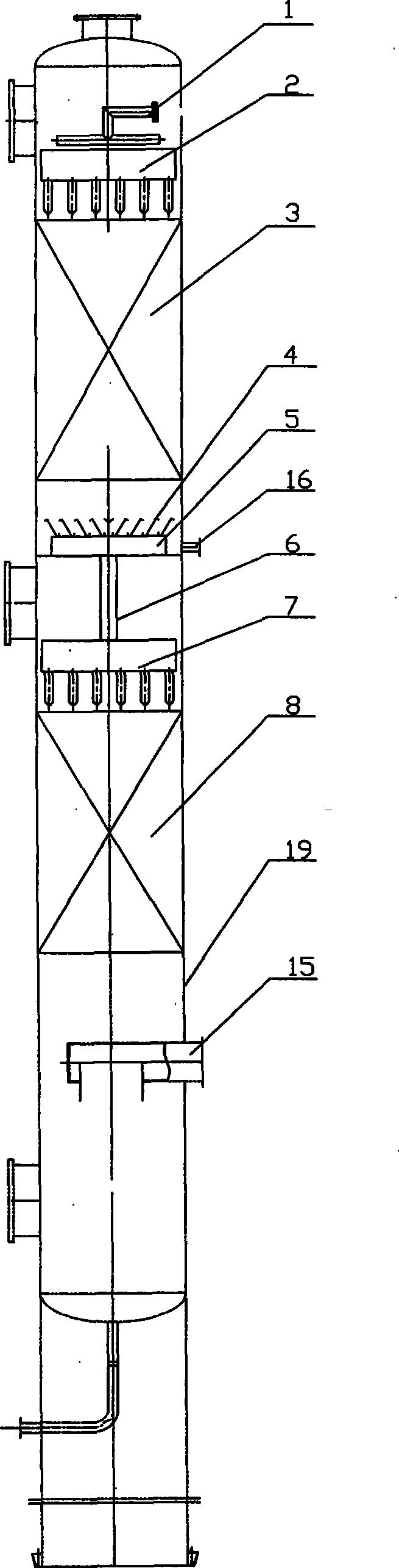
[0017] Embodiment 1, a kind of TDA dehydration tower, with reference to figure 1 , the top of the tower body 19 is provided with a reflux feed pipe 1, the bottom is provided with a recirculation gas phase inlet 15, the middle part is provided with a coarse TDA feed port 16, and the top of the tower body 19 is provided with an upper wall connected to the reflux feed pipe 1. Distribution tank 2, upper packing layer 3 is arranged under upper distribution tank 2, liquid collecting pan 4 is arranged under upper packing layer 3, liquid collecting tank 5 is fixed under liquid closing pan 4, and coarse TDA feed port 16 communicates with liquid collecting tank 5 , the bottom of the liquid collection tank 5 is provided with a downcomer 6 communicating with it, the downcomer 6 communicates with the lower distribution tank 7 below it, the lower distribution tank 7 is provided with a lower packing layer 8, the upper distribution tank 2 and the lower distribution tank 7 can evenly distribut...

Embodiment 2

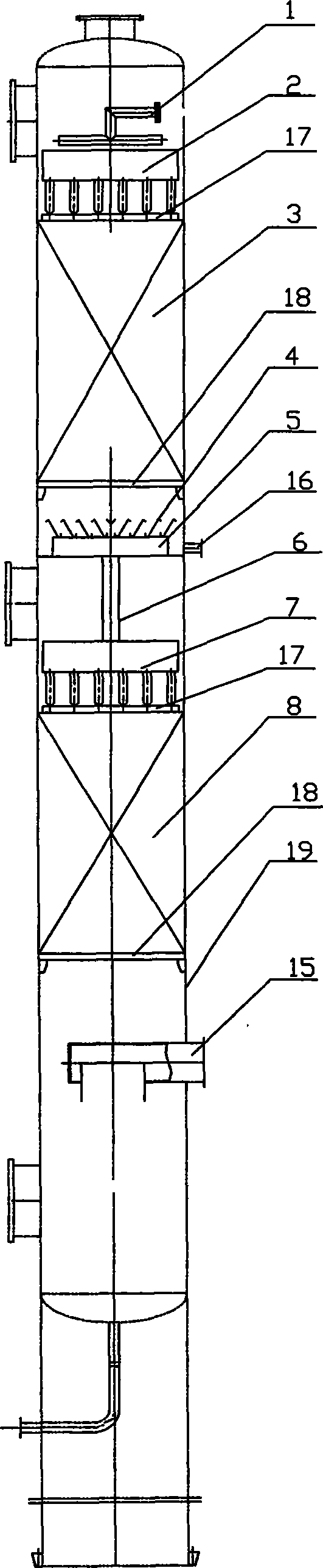
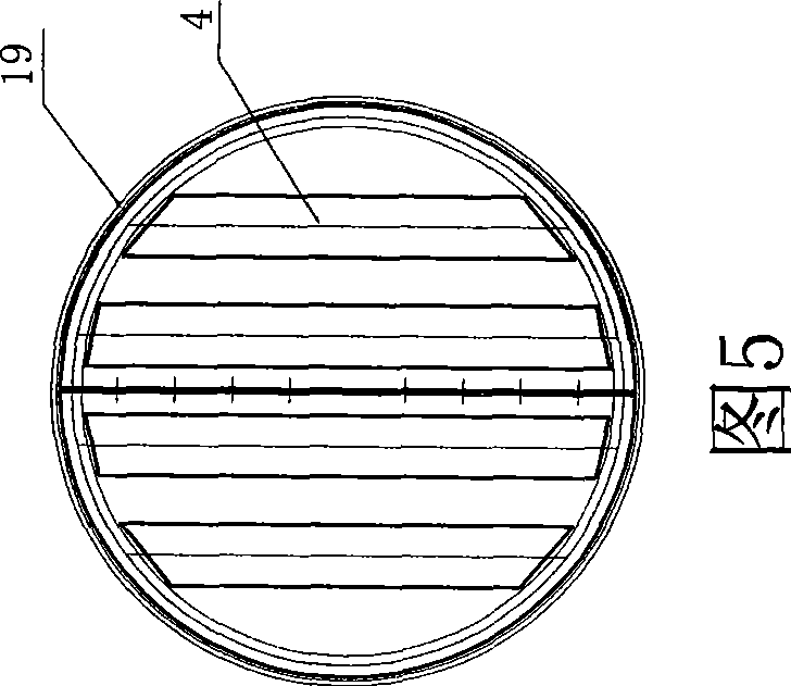
[0018] Embodiment 2, a kind of TDA dehydration tower, with reference to figure 2 , Fig. 3, Fig. 4, Fig. 5, are on the basis of embodiment 1, upper distribution groove 2 and lower distribution groove 7 are to be provided with secondary groove 10 below primary groove 9, and primary groove 9 is rectangular groove body There is a shallow groove 11 with jagged edges fixed in the middle, and the bottom of the rectangular groove is separated by a first-level distribution opening 12. The second-level groove 12 is composed of interconnected grooves 13, and the groove body 13 is directly opposite to the first-level distribution opening 12 above. The bottom surface of the tank body 13 is distributed with secondary distribution holes 14, and the upper packing layer 3 is a stainless steel wire mesh corrugation composed of stainless steel wire mesh corrugated sheets vertically arranged and stacked between the upper packing pressure ring 17 and the lower packing support ring 18. Disc-shaped...


PUM


Abstract

The invention disclose a TDA dehydrating tower, which comprises a tower body, a circumfluence supply pipe, a recycle gas phase inlet and a TDA feeding hole. An upper distributing groove communicated with the circumfluence supply pipe is formed at the top in the tower body, an upper packing layer is arranged below the upper distributing groove, a liquid catch plate is arranged at the lower part of the upper packing layer, a liquid receiving tank is fixed at the lower part of the liquid catch plate, a liquid downtake communicated thereof is arranged at the bottom of the liquid receiving tank, the liquid downtake is communicated with a lower distributing groove formed at the lower part of the liquid downtake, and a lower packing layer is arranged at the lower part of the lower distributing groove. The TDA dehydrating tower has the advantages of simple structure, easy disassembly and assembly, low cost, high degree of the heat change and quality change of two phases of gas and liquid, good separating effect and high efficiency.

Description

technical field [0001] The invention belongs to the technical field of chemical equipment, and in particular relates to a TDA dehydration tower. Background technique [0002] In the production process of tolenediamine (TDA), a large amount of water will inevitably be produced, and in the phosgenation process of tolenediamine, even a small amount of water will cause yield loss and equipment corrosion. Therefore the water in the toluenediamine must be removed. At present, the method of dehydrating TDA in China adopts the rectification method of plate floating valve tower. There is a circular valve hole on the floating valve tower tray, and a valve plate that can float up and down in an appropriate range is installed in the hole. When working, the gas flows from The valve hole rises, opens the valve plate, passes through the annular gap, and then blows into the liquid layer in the horizontal direction to form foam to achieve the purpose of absorption. The float valve is the ga...

Claims


Application Information

Patent Timeline
IPC IPC(8): B01D3/14C07C209/84C07C211/51
Inventor 林生财姜同坤郭文满吕来军赵文涛
Owner YANTAI JULI ISOCYANIC ESTER
Why Eureka
Try Eureka