

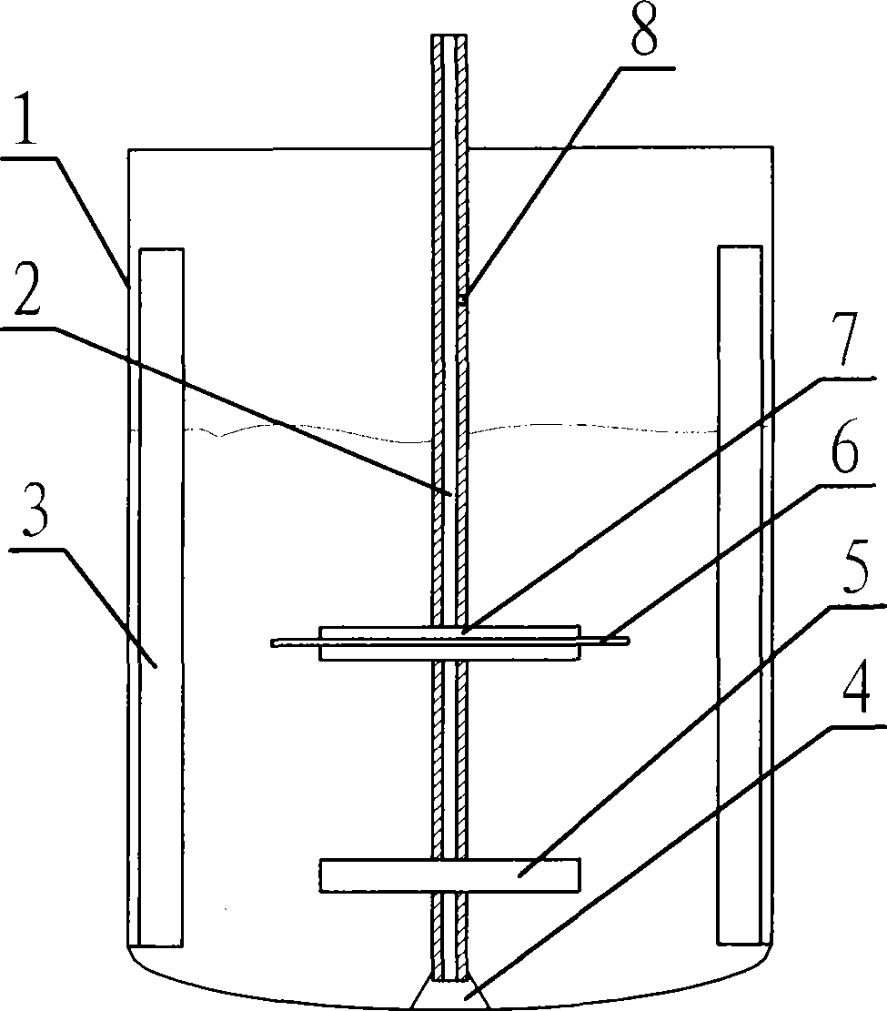
Self-suction mixing reactor
A self-priming, reactor technology, applied in chemical/physical/physicochemical fixed reactors, mixers with rotating stirring devices, chemical instruments and methods, etc., can solve the problem of critical speed and suction without research on baffles The influence of the volume, the influence of the lower paddle is not studied, the strength of the stirring shaft is reduced, etc., to achieve the effect of good gas-liquid contact, simple coordination, and improved mass transfer efficiency
- Summary
- Abstract
- Description
- Claims
- Application Information
AI Technical Summary
Problems solved by technology
Method used
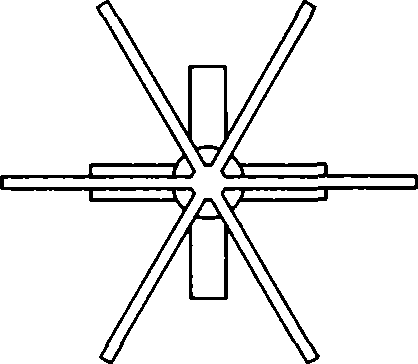
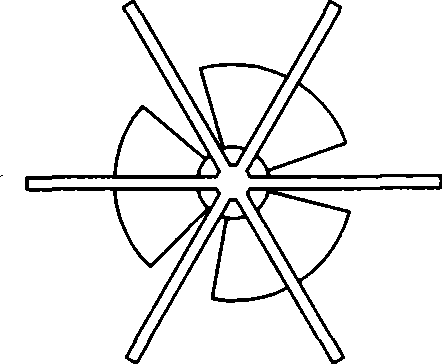
Image

Examples
example 1
[0036] The dichlorobenzene potassium salt carboxylation reaction device with a diameter of 0.7m and an effective volume of 200L is agitated by a double-blade paddle impeller with a rotation speed of 200rpm and a reaction time of 16 hours. Using a self-priming stirred gas-liquid reactor, the reaction time is shortened to 8 hours under the condition of constant rotation speed, and the by-products are reduced, so that the consumption of raw materials is reduced by 30%.
example 2
[0038] The dichlorophenol potassium salt carboxylation reaction device with an effective volume of 10000L is stirred by a double-bladed paddle impeller with a rotating speed of 200rpm and a reaction time of 18 hours. Using a self-priming stirred gas-liquid reactor, the reaction time is shortened to 9 hours under the condition of constant rotation speed, and the by-products are reduced, so that the consumption of raw materials is reduced by 30%.
example 3
[0040]The dichlorophenol potassium salt carboxylation reaction device with an effective volume of 1000ML adopts double-blade paddle impeller stirring, the rotating speed is 450rpm, and the reaction time is 16 hours. A self-priming stirred gas-liquid reactor is adopted, and the reaction time is shortened to 9 hours at a rotating speed of 200 rpm, basically no tar is generated, and the consumption of raw materials is reduced by 20%.
[0041] In summary, the present invention fully grasps the law of air suction control, makes the coordination of air suction volume, stirring speed, and stirring energy consumption simple, makes the gas-liquid contact good, the mass transfer efficiency is greatly improved, and the chemical reaction is more complete, thereby greatly The reaction time is shortened, so that the yield of the product is significantly increased; and the form of paddle stirring is not limited, which can fully meet the needs of different stirring.
PUM
 Abstract
Description
Claims
Application Information