
Transfer case for a motor vehicle powertrain

一种传动系、分动箱的技术,应用在传动装置零件、机械设备、车辆部件等方向,能够解决增加油耗、加大噪音等问题,达到噪声消除、控制系统特征消除的效果

Inactive Publication Date: 2009-06-03
FORD GLOBAL TECH LLC
View PDF6 Cites 15 Cited by
  • Summary
  • Abstract
  • Description
  • Claims
  • Application Information

AI Technical Summary

Problems solved by technology

[0006] This action creates a continuing drag on the drivetrain components, increasing fuel consumption and increasing noise and noise amplification in the drivetrain

Method used


Image

  • Transfer case for a motor vehicle powertrain
  • Transfer case for a motor vehicle powertrain
  • Transfer case for a motor vehicle powertrain

Examples


Embodiment Construction

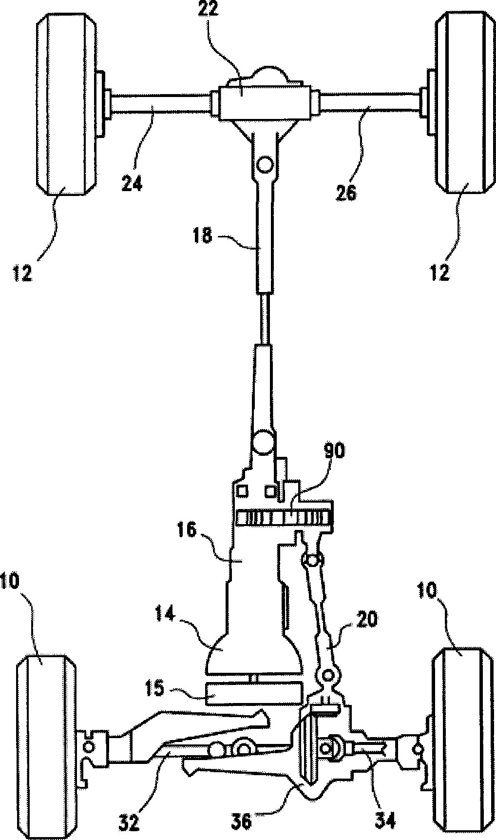
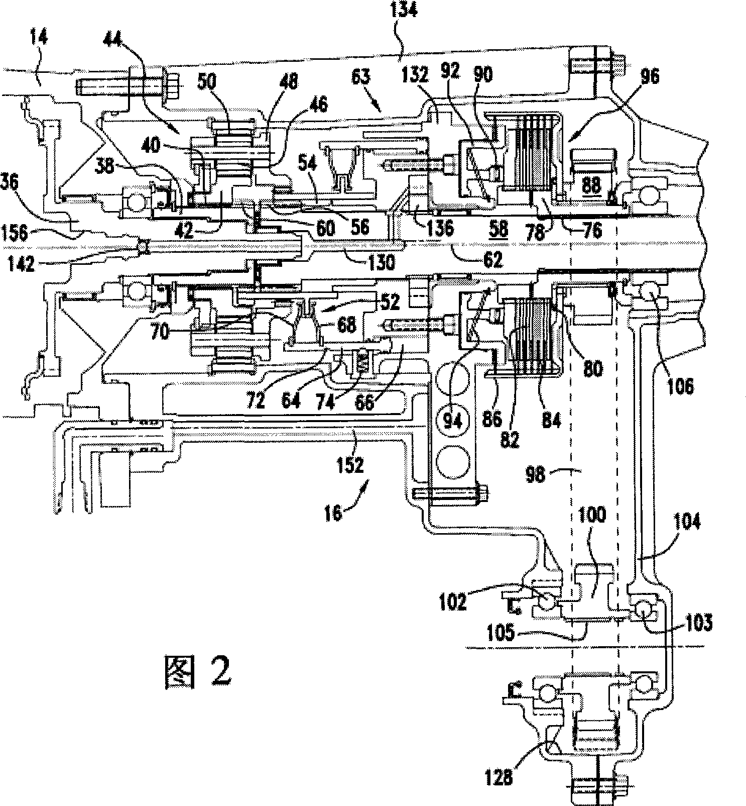
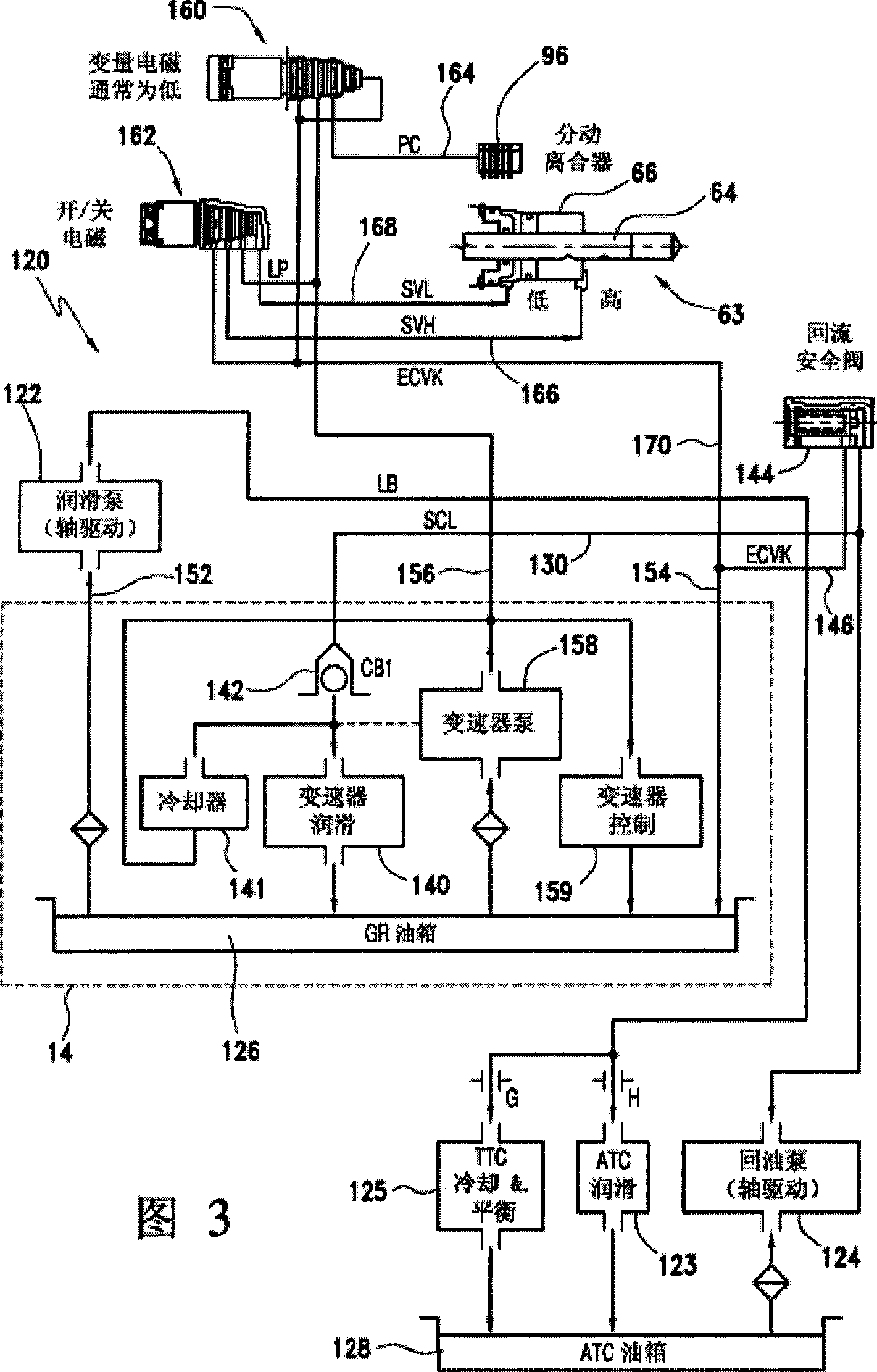
[0018] Referring now to the accompanying drawings, figure 1 A motor vehicle driveline to which the invention may be applied is illustrated by way of example. The drive train includes front and rear wheels 10, 12, a power transmission 14 driven by an engine 15 for various forward and reverse drive ratios, and a transfer for continuously drivable connection of the transmission output to a rear drive shaft 18 Box 16. The transfer case 16 continuously connects the transmission output to the rear drive shaft 18 and selectively connects the transmission output to the front drive shaft 20 when the four wheel drive mode of operation is selected either manually or electrically. Shaft 18 transmits power to a rear wheel differential 22 placed within the differential case, from which power is differentially transmitted to rear wheels 12 via drive shafts 24 , 26 . The front wheels are drivably connected to right and left hand half shafts 32 , 34 to which power is transmitted from drive s...


PUM


Abstract

A motor vehicle powertrain includes a multiple speed transmission including a first lube circuit that supplies hydraulic lubricant to components of the transmission, a first oil sump, and a first pump driveably connected to an engine for supplying oil at a first pressure to the lube circuit, a transfer case including a first output, a second oil sump located in the transfer case, a second pump located in the transfer case and driveably connected to the first output, and a check valve for alternately opening and closing a connection between the first pump and the lube circuit and for opening and closing a connection between the second pump and the lube circuit in response to differential pressure between an outlet of the first pump and an outlet of the second pump.

Description

technical field [0001] This invention relates generally to powertrains for motor vehicles, and more particularly to powertrains having a transfer case that transmits power to the front and rear wheels. Background technique [0002] The transfer case may include planetary gears for producing a "high" range where the output is driven at the same speed as the input, or a "low" range where the output is driven to slower than the input speed. The driver of the vehicle typically manually selects the 4x2 (high), 4x4 (high) and 4x4 low states of the transfer case via a lever or switch. The first position of the lever will cause the gear selector in the transfer case to direct power from the transmission output to the rear transaxle, 4×2 drive mode. The second position of the lever will cause the transfer case to send power to the front and rear transaxles, 4×4 drive mode. The final position moves the transfer case into a low range. [0003] A conventional rear-wheel drive, on-de...

Claims


Application Information

Patent Timeline
Patent Type & Authority Applications(China)
IPC IPC(8): B60K17/344F16H57/04F16D48/00
CPCF16H57/0483F16H57/0434F16H57/0409B60R17/00F01M1/16F01M1/20F16H57/0447
Inventor 斯蒂芬·G·托马斯安德里亚斯·E·皮雷克斯马修·D·哈蒙德斯蒂芬·A·福瑞特莫尼卡·R·德格莱芬瑞德格雷戈里·D·戈莱斯基奇普·哈廷尔杰弗里·E·毛瑞尔
Owner FORD GLOBAL TECH LLC
Learn More