Method for making carbon fibre-reinforced parts of composite material
A technology of composite materials and manufacturing methods, applied to parts of brakes, brake discs, non-woven fabrics, etc., can solve problems such as uneven materials and increased manufacturing costs
- Summary
- Abstract
- Description
- Claims
- Application Information
AI Technical Summary
Problems solved by technology
Method used
Image
Examples
Embodiment 1
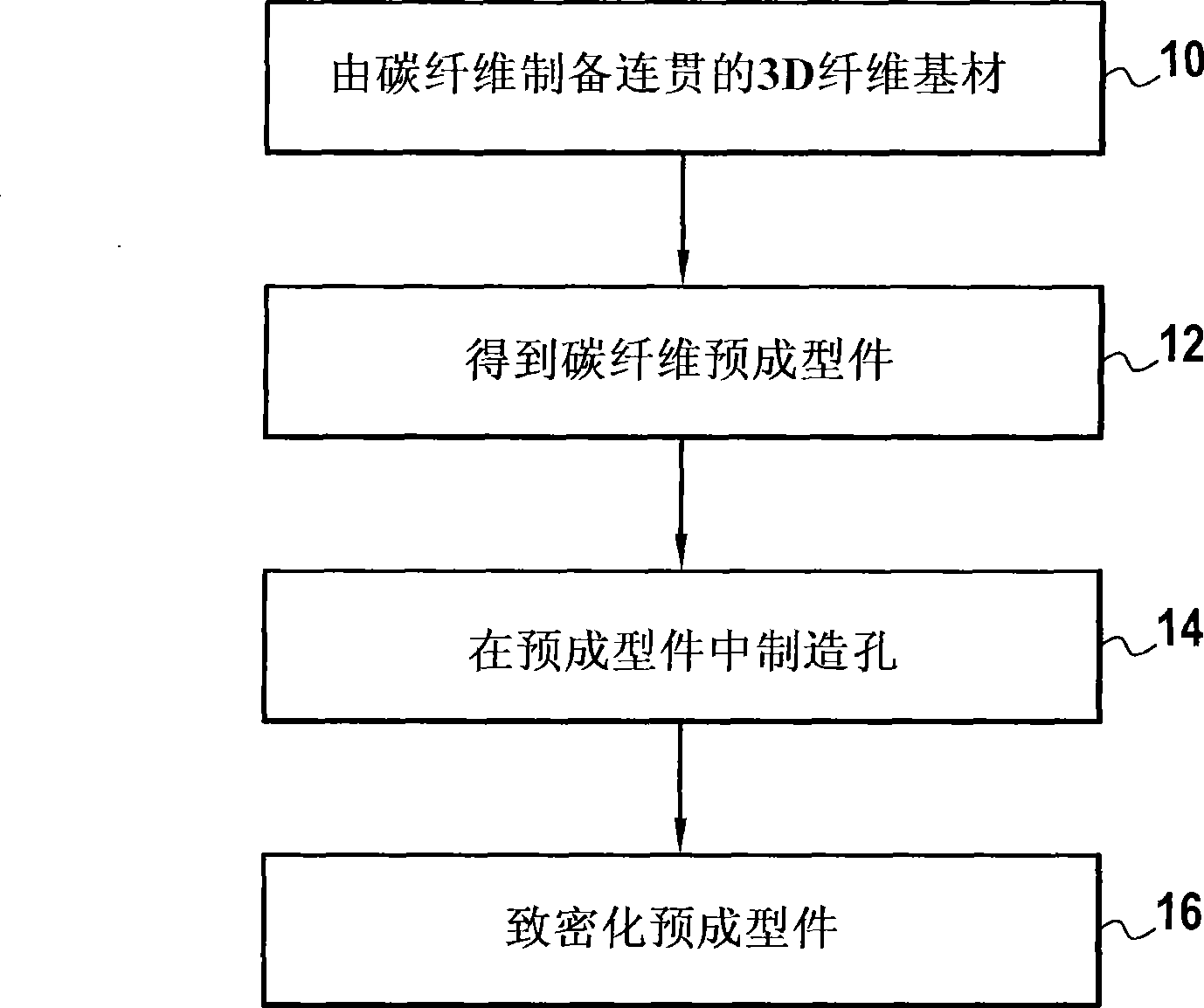
[0092] Carbon fiber preforms for aircraft brake discs are manufactured as follows:
[0093] nD woven sheets of peroxidized PAN fibers are formed by draping and light needling 3 UD woven sheets forming an angle of ±60° to each other;
[0094] Formation of 3D fiber preforms by overlapping and needling together cloth layers obtained from nD woven sheets using the method of document US 5 792 715;
[0095] cutting out a disc-shaped portion from said 3D fiber substrate; and
[0096] • Carbonization of the cut-out parts to obtain disc-shaped fiber preforms made of carbon fibres.
[0097] The resulting preform was densified by CVI in a conventional manner to obtain a carbon matrix using a method comprising a first densification period of 500 hours (h), skin scraping, and a second densification of 75 h.
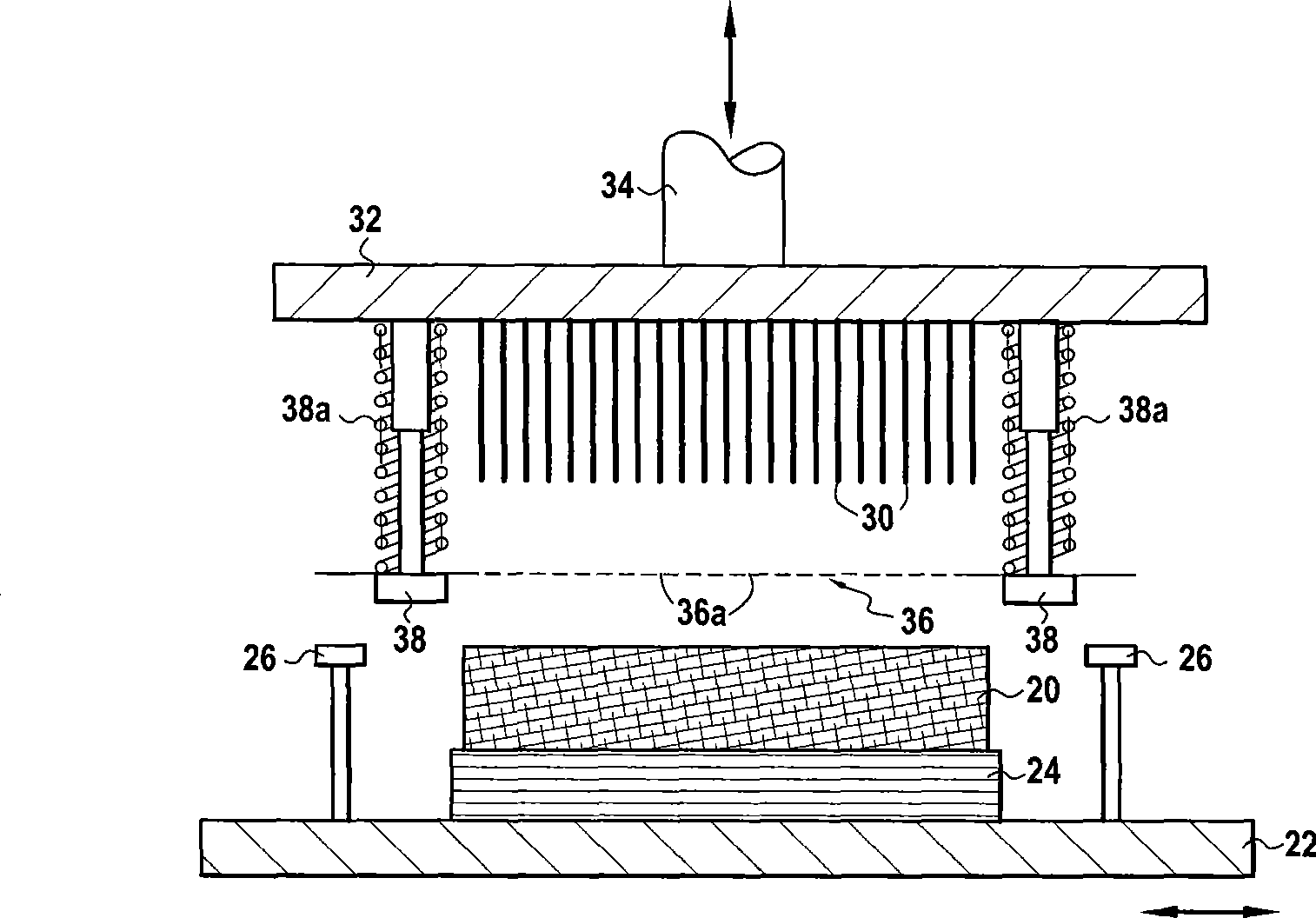
[0098] use as figure 2 The device shown pierces other preforms obtained in this way after the carbonization step to form holes, said device being equipped with image 3 Shown is ...
Embodiment 2
[0106] Carbon fiber preforms for aircraft brake discs were produced as in Example 1, some preforms were used to manufacture the rotating disc, other preforms were used to manufacture the end discs, and still others were used to manufacture the center discs (wherein Brakes consist of stacks with alternating fixed and rotary discs).
[0107] The preforms for each type of disk were processed as follows:
[0108] A) With needles as used in Example 1, with 4 holes / cm per surface 2 A density of 0.00000000000000000000000000000000000000000000000000000000000000000000000000000000000000000000000000000000000000000000000000000000000010000000000000 whom formed holes whose penetration was such that the ends of the needles protruded a length of 6.63 mm to ensure that the first burr of each needle went directly through the preform and out from the opposite surface;
[0109] B) Pores are formed as in A), but with a density of 2 pores / cm per surface 2 ;
[0110] C) Holes are formed on only on...
Embodiment 3
[0123] Carbon fiber preforms for aircraft brake discs were fabricated as in Example 2.
[0124] Holes were formed in the preforms using various types of barbed needles supplied by suppliers Foster Needles Co. and Groz Beckert. Densify the perforated preform and process the turntable, center and end disks as in Example 2. Table II gives the relative density values for each type of disc measured with different types of needles and different hole densities. The first 4 rows of needles are supplied by the supplier Foster Needle Co. with a working section height of 0.45 mm to 0.55 mm, and the other needles are supplied by the supplier Groz Beckert and have a working section height of 0.7 mm to 1 mm . For comparison, the average relative density of disks manufactured in the same manner, but without holes formed in the preform was also measured.
[0125] Table II
[0126] needle type Hole density (hole) Number of piercing surfaces turntable Center fix Final or...
PUM
| Property | Measurement | Unit |
|---|---|---|
| diameter | aaaaa | aaaaa |
| diameter | aaaaa | aaaaa |
| power | aaaaa | aaaaa |
Abstract
Description
Claims
Application Information
 - R&D
- Intellectual Property
- Life Sciences
- Materials
- Tech Scout
- Unparalleled Data Quality
- Higher Quality Content
- 60% Fewer Hallucinations
Browse by: Latest US Patents, China's latest patents, Technical Efficacy Thesaurus, Application Domain, Technology Topic, Popular Technical Reports.
© 2025 PatSnap. All rights reserved.Legal|Privacy policy|Modern Slavery Act Transparency Statement|Sitemap|About US| Contact US: help@patsnap.com


