Method for 3D printing of a composite structure

A 3D printing and composite structure technology, applied in the field of 3D printing, can solve the problems of restricting the application and promotion of 3D printing, low mechanical strength, and non-wear resistance, and achieve the goals of saving traditional processing cycles, increasing manufacturing costs, and improving structural strength. Effect

Inactive Publication Date: 2020-11-10
代庆钢
View PDF9 Cites 0 Cited by
  • Summary
  • Abstract
  • Description
  • Claims
  • Application Information

AI Technical Summary

Problems solved by technology

[0003] Non-metallic material printing is now the mainstream material for 3D printing. However, due to the inherent shortcomings of non-metallic materials such as plastics with low mechanical strength, wear resistance, and thermal deformation, the application and application of 3D printing in the manufacture of industrial structural parts are greatly limited. to promote

Method used


Image

  • Method for 3D printing of a composite structure
  • Method for 3D printing of a composite structure
  • Method for 3D printing of a composite structure

Examples


specific Embodiment 1

[0029] Print a cube shape with a side length of 10 cm, use Somos 11122 material as the printing material, and print a solid part as a comparison example.

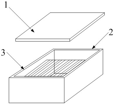
[0030] The cube is decomposed into a prefab with a wall thickness of 1 cm and a semi-open cavity with a side length of 8 cm and a top cover with a thickness of 1 cm.

[0031] After printing out the prefabricated parts, arrange multiple layers of 7628-standard glass fiber cloth in parallel in the cavity, with an interval of 1 cm between the glass fiber cloths. Holes can be opened on the glass fiber cloth to facilitate the flow of semi-solid epoxy resin. After the arrangement is completed, the semi-solid epoxy resin mixed with curing agent is injected to fill the cavity, and a certain cavity space can be reserved according to the expansion characteristics of the epoxy resin after curing. In this embodiment, novolac epoxy resin and aromatic amine curing agent are mixed according to 100:40 parts by weight and then cured and fil...

specific Embodiment 2

[0035] Print a cube shape with a side length of 10 cm, use PLA (Polylactide, polylactic acid), that is, corn starch resin material as the printing material, and print a solid part as a comparison example.

[0036] The cube is decomposed into a prefab with a wall thickness of 1 cm and a semi-open cavity with a side length of 8 cm and a top cover with a thickness of 1 cm.

[0037] After printing out the prefabricated parts, arrange multiple layers of 7628-standard glass fiber cloth in parallel in the cavity, with an interval of 1 cm between the glass fiber cloths. Holes can be opened on the glass fiber cloth to facilitate the flow of semi-solid epoxy resin. After the arrangement is completed, the semi-solid epoxy resin mixed with curing agent is injected to fill the cavity, and a certain cavity space can be reserved according to the expansion characteristics of the epoxy resin after curing. In this embodiment, novolac epoxy resin and aromatic amine curing agent are mixed accordi...

specific Embodiment 3

[0041] Print a cube shape with a side length of 10 cm, use ABS (Acrylonitrile Butadiene Styrene), acrylonitrile-butadiene-styrene ternary block copolymer as the printing material, and print a solid part as a comparison example.

[0042] The cube is decomposed into a prefab with a wall thickness of 1 cm and a semi-open cavity with a side length of 8 cm and a top cover with a thickness of 1 cm.

[0043] After printing out the prefabricated parts, arrange multiple layers of 7628-standard glass fiber cloth in parallel in the cavity, with an interval of 1 cm between the glass fiber cloths. Holes can be opened on the glass fiber cloth to facilitate the flow of semi-solid epoxy resin. After the arrangement is completed, the semi-solid epoxy resin mixed with curing agent is injected to fill the cavity, and a certain cavity space can be reserved according to the expansion characteristics of the epoxy resin after curing. In this embodiment, novolac epoxy resin and aromatic amine curing ...


PUM


Abstract

The invention discloses a method for 3D printing of a composite structure. The method comprises the following steps that a structure is decomposed into a prefabricated part and a top cover according to the component structure to be printed, and the prefabricated part is a semi-open cavity capable of being completely closed by the top cover; a prefabricated part is printed by adopting a 3D printingtechnology; fiber cloth is arranged in the semi-open cavity, and then a semi-solid filling body is injected into the cavity; and after the semi-solid filling body is cooled to be solidified, the topcover continues to be printed on the boundary of the prefabricated part, and the complete component structure is formed. By the adoption of the method for 3D printing of the composite structure, the structural strength of a component can be greatly improved, particularly, the manufacturing cost cannot be greatly increased for complex and difficult-to-machine shapes, the requirement for the structural component in the enterprise research and development stage or small-batch production is met, the cost is saved, the traditional machining period is shortened, and the economic benefits are obvious.

Description

technical field [0001] The invention belongs to the technical field of 3D printing and relates to a 3D printing method, in particular to a 3D printing composite structure method. Background technique [0002] 3D printing materials have become the main bottleneck restricting the development of 3D printing, and it is also the key point and difficulty of 3D printing breakthrough innovation. Only by developing more new materials and new processes can the application field of 3D printing technology be expanded. At present, 3D printing materials mainly include polymer materials, metal materials, ceramic materials, etc. [0003] Non-metallic material printing is now the mainstream material for 3D printing. However, due to the inherent shortcomings of non-metallic materials such as plastics with low mechanical strength, wear resistance, and thermal deformation, the application and application of 3D printing in the manufacture of industrial structural parts are greatly limited. prom...

Claims


Application Information

Patent Timeline
IPC IPC(8): B29C64/171B33Y10/00
CPCB33Y10/00B29C64/171
Inventor 代庆钢
Owner 代庆钢
Why Eureka
Try Eureka