Layered drainage structure of underground powerhouse chamber of hydropower station in water-rich region and construction method thereof

A technology for underground powerhouses and drainage structures, which is applied in infrastructure engineering, waterway systems, and sewage discharge. It can solve problems that affect the safe operation of underground powerhouses, high operating costs, and large pumping and drainage volumes, so as to reduce pumping and drainage volumes and ensure construction safety. , reduce the effect of configuration

Active Publication Date: 2009-06-03
POWERCHINA HUADONG ENG COPORATION LTD
View PDF0 Cites 5 Cited by
  • Summary
  • Abstract
  • Description
  • Claims
  • Application Information

AI Technical Summary

Problems solved by technology

For the caverns of underground powerhouses with good geological conditions and low groundwater, the amount of water seepage in the surrounding rocks is not large. When the surrounding rocks are in the rocks of the zone, the seepage of the surrounding rock is large, and the centralized pumping and drainage method is used to pump a large amount of water and high operating costs. Insufficient equipment configuration or loss of power supply may cause water to flood the plant and affect the safe operation of the underground plant.

Method used


Image

  • Layered drainage structure of underground powerhouse chamber of hydropower station in water-rich region and construction method thereof
  • Layered drainage structure of underground powerhouse chamber of hydropower station in water-rich region and construction method thereof
  • Layered drainage structure of underground powerhouse chamber of hydropower station in water-rich region and construction method thereof

Examples


Embodiment Construction

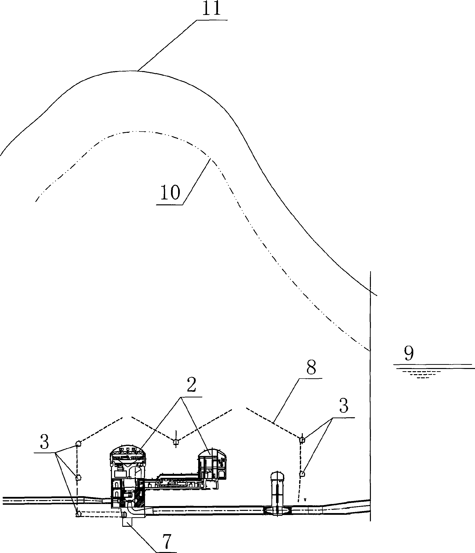
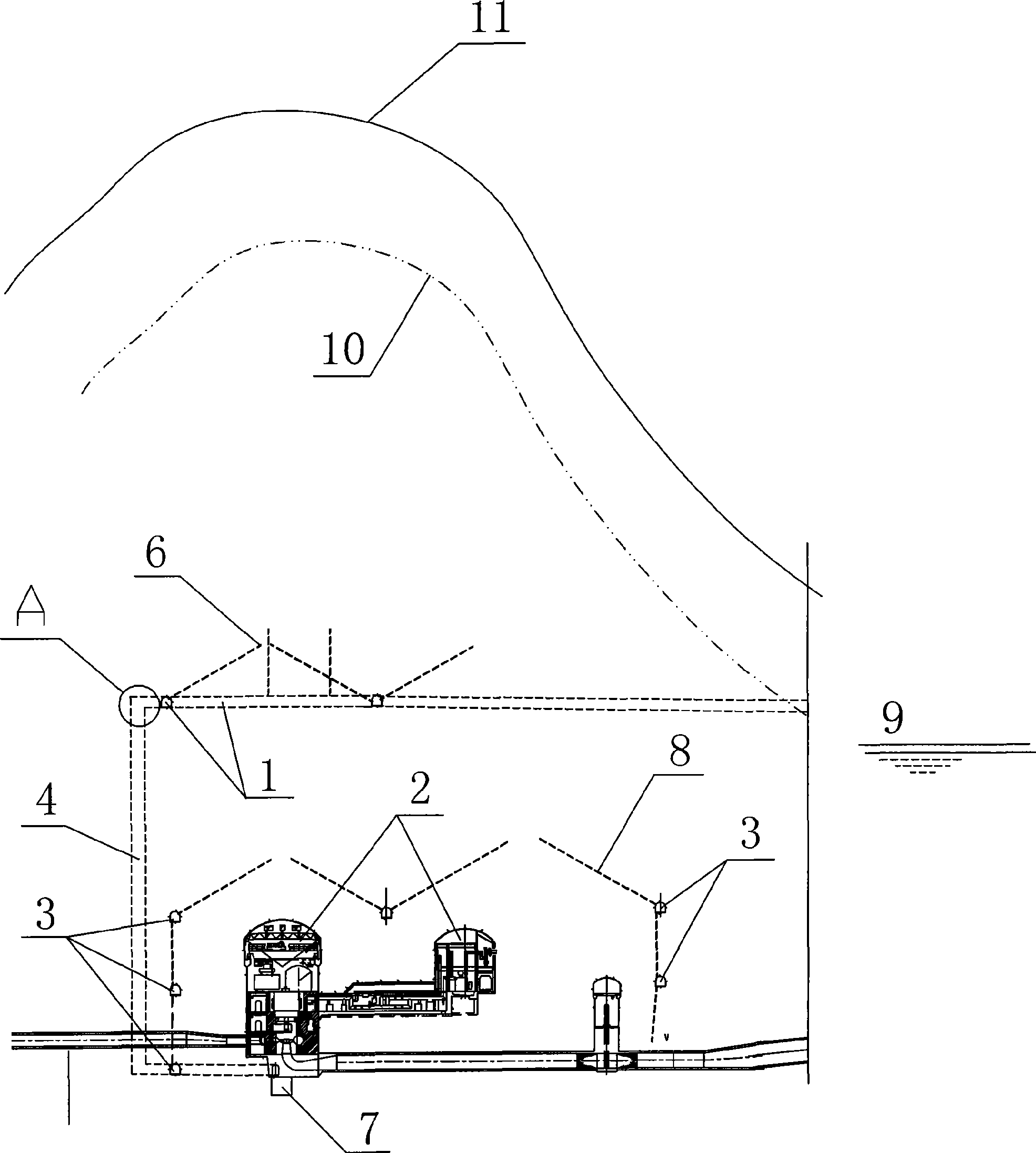
[0018] Such as figure 2 As shown, this embodiment is applied to the caverns of underground powerhouses of hydropower stations in water-rich areas, and adopts a layered drainage method. The cavern 2 of the underground powerhouse of the hydropower station is deeply buried, and is built in a mountain below the groundwater level 10. The downstream of the ground line 11 of the mountain body is a river channel, and the water level 9 in the river channel is higher than the cavern 2 of the underground powerhouse. A water collection well 7 is built at the bottom of the cavern 2 of the underground powerhouse and is equipped with power pumping and drainage equipment. Several layers of drainage corridors 3 are set around the cavern 2 of the underground powerhouse. The connected drainage holes 8 and the seepage of the drainage gallery 3 all flow into the sump 7. The feature of the present invention is: in the mountain above the cavern 2 of the underground powerhouse, which is higher than...


PUM


Abstract

The invention relates to a layered drainage structure of an underground powerhouse chamber of a hydropower station in a water-rich region and a construction method thereof. The technical problem to be solved by the invention is to provide the layered drainage structure of the underground powerhouse chamber of the hydropower station in the water-rich region and the construction method thereof, and the invention aims at effectively reducing the drainage and discharge capacity of the underground powerhouse, reducing the operation cost by power-driven drainage and discharge, and ensuring the safe construction of the underground powerhouse and a safe running period. The technical proposal for solving the problem is as follows: the layered drainage structure of the underground powerhouse chamber of the hydropower station in a water-rich region with great buried depth is provided with the underground powerhouse chamber, the bottom part thereof is provided with a water-collecting well and a power-driven drainage and discharge device, a plurality of layers of drainage galleries are arranged around the underground powerhouse chamber, the various layers of the drainage galleries are all communicated with the water-collecting well, and the layered drainage structure is characterized in that a layer of intercepting gallery is arranged in a mountain body above the underground powerhouse chamber which is higher than the water level of a river course, and the intercepting gallery is communicated with the water-collecting well through a vertical or inclined connecting gallery. The invention can be used for water conservancy and hydropower underground powerhouse chamber projects.

Description

technical field [0001] The invention relates to a layered drainage structure and a construction method for an underground powerhouse cavern of a hydropower station in a water-rich area. It is suitable for cavern projects of underground powerhouses for water conservancy and hydropower. Background technique [0002] The turbines of hydropower stations all have a certain suction height requirement, and the installation elevation of the unit is low. For the underground powerhouse, the elevation of the bottom of the cavern is lower than the elevation of the water level of the river. Due to the low elevation of the cavern of the underground powerhouse, which is located below the groundwater level of the mountain and the water level of the river, the surrounding rock will seep into the powerhouse during the construction and operation period of the underground powerhouse. In order to maintain a good operating environment for underground powerhouses, drainage corridors are generally...

Claims


Application Information

Patent Timeline
Patent Type & Authority Applications(China)
IPC IPC(8): E03F1/00E02D19/12
Inventor 张春生江亚丽戚海峰应和平
Owner POWERCHINA HUADONG ENG COPORATION LTD
Why Eureka
Try Eureka