Exhaust gas recycling aerostatic bearing and design method thereof

An aerostatic bearing and design method technology, applied to bearings, shafts and bearings, mechanical equipment, etc., can solve problems affecting the measurement accuracy of instruments and equipment, eliminate the impact of gas disturbance on the measurement environment, improve measurement accuracy, and optimize structure effect

Active Publication Date: 2009-06-03
BEIJING INSTITUTE OF TECHNOLOGYGY
View PDF0 Cites 13 Cited by
  • Summary
  • Abstract
  • Description
  • Claims
  • Application Information

AI Technical Summary

Problems solved by technology

In precision measurement, especially in optical precision measurement, air flow disturbance will produce micro-vibration ...

Method used


Image

  • Exhaust gas recycling aerostatic bearing and design method thereof
  • Exhaust gas recycling aerostatic bearing and design method thereof
  • Exhaust gas recycling aerostatic bearing and design method thereof

Examples


Embodiment 1

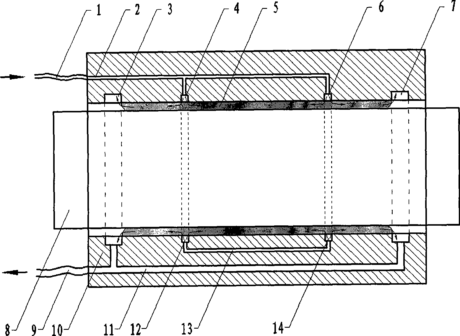
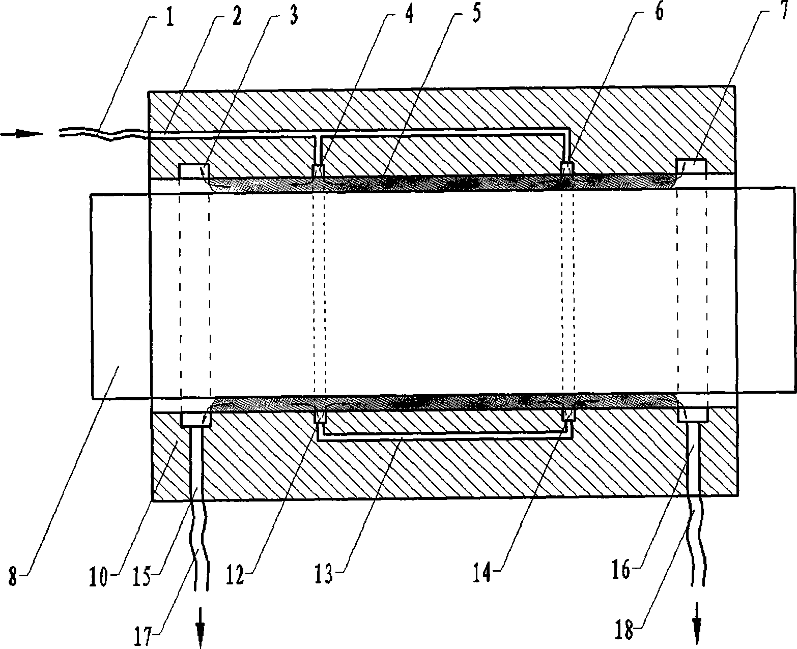
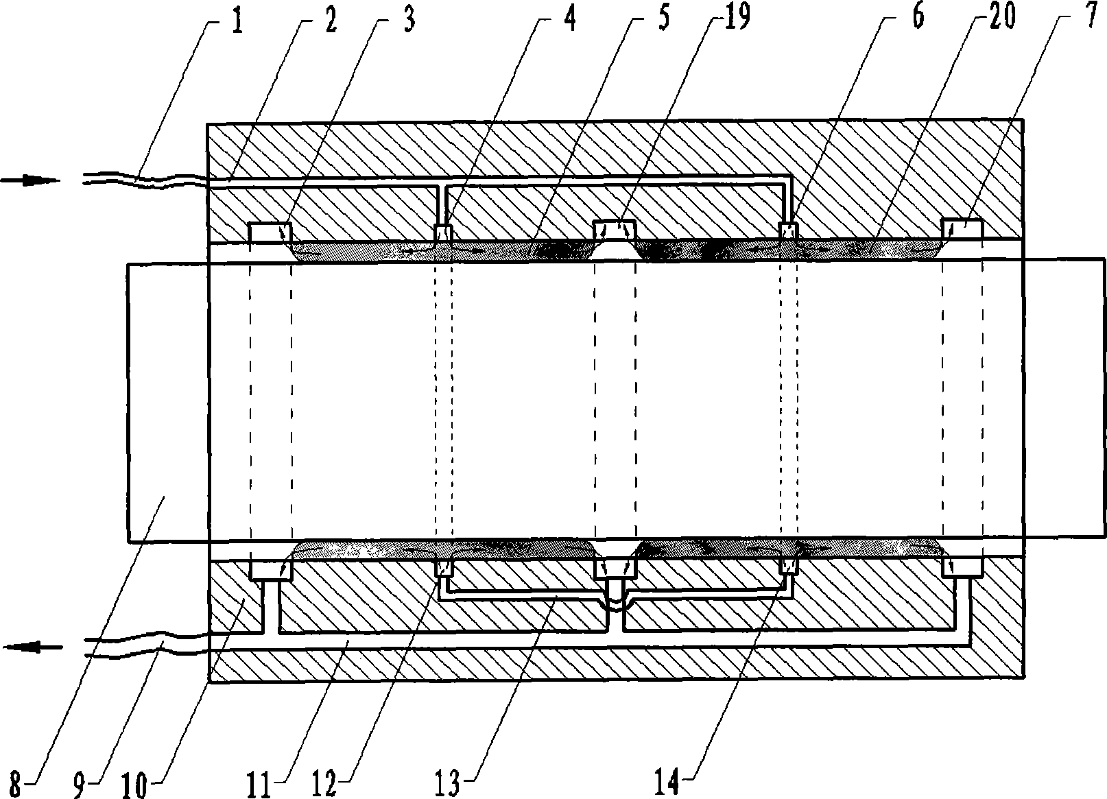
[0028] The structure of Embodiment 1 of the present invention is as Figure 5 As shown, an aerostatic linear bearing device that can recover exhaust gas includes an external air supply pipe 1, an external exhaust pipe 9, a main shaft 8, and a bearing sleeve 10. Air supply holes 4, Air supply hole 12, air supply hole 6, air supply hole 14, zero pressure groove loop 3, zero pressure groove loop 19, zero pressure groove loop 7, when the bearing is working, the adjacent zero pressure groove loop 3, zero pressure groove loop A high-pressure area 5 and a high-pressure area 20 are formed between the pressure groove loop 7, the zero-pressure groove loop 7, and the zero-pressure groove loop 19, and an air supply pipeline 2, an air supply loop 13, and an exhaust pipeline are arranged inside the bearing sleeve 10. 11. The air supply circuit 13 connects the air supply hole 4, the air supply hole 12, the air supply hole 6, and the air supply hole 14. The external air supply pipe 1 and the ...

Embodiment 2

[0031] The structure of Embodiment 2 of the present invention is as Figure 6 As shown, the difference from Example 1 is that the main shaft 8 is circular, and the high-pressure air enters the air supply pipe 2 from the external air supply pipe 1, flows in the air supply circuit 13, and passes through the air supply hole 4, the air supply hole 12, and the air supply hole 6. , the air supply hole 14, the outflow bearing sleeve 10 is sprayed to the surface of the main shaft 8, under the action of gas pressure, the main shaft 8 is separated from the bearing sleeve 10, and the high-pressure gas enters the gap between the main shaft 8 and the bearing sleeve 10 and forms a high-pressure zone 5, High pressure zone 20. When the bearing is working, an extremely thin layer of gas lubricating film is formed between the main shaft 8 and the bearing sleeve 10, and the main shaft 8 can rotate in the bearing sleeve 10 almost without friction, and the working process is the same as that of em...


PUM


Abstract

The invention belongs to the technical field of precision machining and measurement, which relates to a technology of a pneumatic bearing. The aerostatic bearing comprises a main shaft, a bearing sleeve and an external exhaust manifold. A closed zero-pressure trough loop is equipped in the bearing sleeve to collect all exhaust gas, the zero-pressure trough loop on both ends of the bearing sleeve further is located in the high-pressure region between two components and separated from the external environment; the zero-pressure trough loop is connected with the external exhaust manifold through an exhaust manifold or an air vent directly, and all exhaust gas is inducted out and recycled by the external exhaust manifold. The invention firstly proposes that a closed zero-pressure trough loop is arranged in the aerostatic bearing to lead the exhaust gas and separate the exhaust gas from the measurement environment. Therefore, the influence of the measurement environment caused by the gas turbulence due to the discharge of the exhaust gas is eliminated, the measurement precision of the measuring system is remarkably improved, the structure of the aerostatic bearing is optimized, and dust is effectively from entering the bearing from the air vent, thereby the exhaust gas recycling aerostatic bearing can be widely applied to the precision machining and measurement devices.

Description

technical field [0001] The patent of the invention relates to an aerostatic bearing technology, which can be widely used in precision machining and measurement equipment, and belongs to the technical field of precision machining and measurement. technical background [0002] With the development of ultra-precision machining and testing technology, the realization of ultra-high-precision rotary motion and linear motion is becoming more and more important. Due to its high precision and long life, aerostatic bearings are widely used in modern ultra-precision machining machine tools and measuring instruments to achieve high-precision rotary and linear motion. [0003] The existing aerostatic bearing generally consists of a bearing sleeve and a main shaft. An air supply hole with a very small diameter is processed on the working surface of the bearing sleeve, and the main shaft is installed in the cavity of the bearing sleeve. A high pressure zone is formed in the gap with the ...

Claims


Application Information

Patent Timeline
IPC IPC(8): F16C32/06
Inventor 赵维谦刘超邱丽荣沙定国
Owner BEIJING INSTITUTE OF TECHNOLOGYGY
Why Eureka
Try Eureka