Energy-saving lamp automatic assembly line

A technology of automatic assembly and energy-saving lamps, applied in the field of machinery, can solve the problems that the cam rotation is not easy to control the up and down movement of the transmission rod, curb the large-scale automatic production of energy-saving lamps, and replace parts for defective products. Good welding effect and uniform tightening force

Inactive Publication Date: 2009-06-03
ZHEJIANG SHENDU OPTOELECTRONICS TECH
View PDF5 Cites 20 Cited by
  • Summary
  • Abstract
  • Description
  • Claims
  • Application Information

AI Technical Summary

Problems solved by technology

Existing tests generally test energy-saving lamps manually or semi-manually, which is easily affected by human factors during the test process, and generally has a high rate of defective products, poor detection pass rate, poor quality stability, and easy product rework. As a result, the production efficiency is low, and due to the certain radiation generated during the testing process, the operators have been in this production environment for a long time, which has a certain degree of physical and mental damage. This also curbs the large-scale automatic production of energy-saving lamps to a certain extent. develop
[0008] The nailing process of the lamp head is mainly manual. Chinese patent literature Chinese patent number: ZL200720110417.9; authorized announcement number CN201043721Y has disclosed an automatic nailing device for energy-saving lamps, but the cam rotation in this technical solution is not easy to control the up and down movement of the transmission rod. As a result, it often happens that the nailing position does not deviate or the nailing device crushes the lamp head. At this time, the defective products can no longer be repaired by replacing parts, which greatly increases the defective product rate.

Method used


Image

  • Energy-saving lamp automatic assembly line
  • Energy-saving lamp automatic assembly line
  • Energy-saving lamp automatic assembly line

Examples


Embodiment Construction

[0039] The following are specific embodiments of the present invention and in conjunction with the accompanying drawings, the technical solutions of the present invention are further described, but the present invention is not limited to these embodiments.

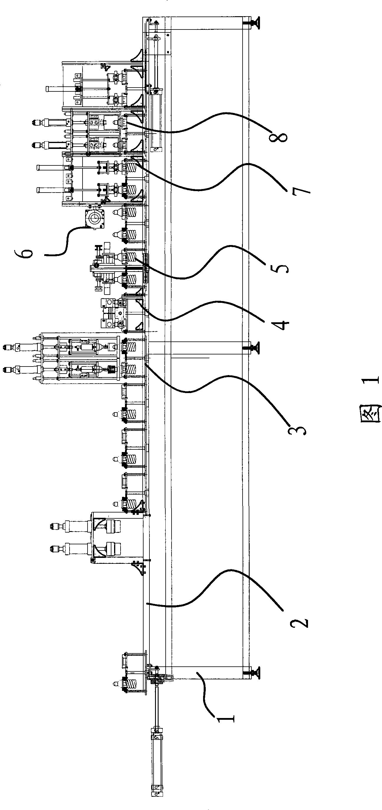
[0040] As shown in Figure 1, the energy-saving lamp automatic assembly line includes a frame 1, an energy-saving lamp assembly transmission system 2 arranged on the frame 1 for transporting energy-saving lamps, and an automatic rotating energy-saving lamp cap device 3 that connects the lamp cap and the lamp body. . Automatic cutting device for energy-saving lamps that automatically cuts excess filament from the lamp cap of energy-saving lamps. 4. Automatic soldering device for energy-saving lamps that automatically welds filaments to the lamp cap. 5. Cooling mechanism 6. Will detect whether the lamp cap and the lamp body are connected A solid energy-saving lamp automatic detection control system 7, an energy-saving lamp aut...


PUM


Abstract

The invention provides an energy-saving lamp automatic assembly line which belongs to the technical field of machine. The energy-saving lamp automatic assembly line solves the problem that the existing energy-saving lamp automatic assembly line adopts manual assembly and has low production efficiency. The energy-saving lamp automatic assembly line is provided with an energy-saving lamp assembly transmission system on a frame. The energy-saving lamp assembly transmission system comprises a middle transmission track and branch transmission tracks. Joint parts of one end of the middle transmission track with two branch transmission tracks are provided with distributing mechanisms which can distribute energy-saving lamps at the middle transmission track to two branch transmission tracks. Each branch transmission track is respectively provided with an automatic rotating energy-saving lamp cap device, an energy-saving lamp automatic filament-cutting device, an energy-saving lamp automatic tin soldering device, an energy-saving lamp automatic detecting and controlling system and an energy-saving lamp automatic nailing device. The energy-saving lamp automatic assembly line is equipped with two sets of assembly devices and realizes the advantages of automatic transmission and assembly, etc.

Description

technical field [0001] The invention belongs to the technical field of machinery and relates to an assembly line, in particular to an automatic assembly line for energy-saving lamps. Background technique [0002] Compared with incandescent lamps, energy-saving lamps have a significant energy-saving effect. The light emitted by each 1 watt of energy-saving lamps is equivalent to the light emitted by 5 to 6 watts of incandescent lamps. application. [0003] Energy-saving lamps include lamp caps, lamp bodies, lamp tubes and filaments. The traditional energy-saving lamp production process consists of main steps such as tightening the lamp cap, cutting the filament, soldering the lamp cap, conformity inspection, and nailing the lamp cap. [0004] The tightening of the lamp cap is all done by hand, so the requirements for the operator are relatively high. If the tightening degree is not enough, the lamp cap is easy to fall and other defects, and the quality defect of not enough ...

Claims


Application Information

Patent Timeline
Patent Type & Authority Applications(China)
IPC IPC(8): H01J9/46H01J9/48
Inventor 张臻
Owner ZHEJIANG SHENDU OPTOELECTRONICS TECH
Why Eureka
Try Eureka