Squeezing roller and rotary drum-type magnetic separator

A magnetic separation device, drum-type technology, applied in the direction of magnetic separation, solid separation, shafts and bearings, etc., can solve the problems of reduced extrusion efficiency, insufficient liquid extrusion, insufficient liquid removal, etc., to ensure durability Sexual, long-term stable liquid extrusion effect

Active Publication Date: 2009-06-03
SUMITOMO HEAVY IND FINETECH
View PDF1 Cites 16 Cited by
  • Summary
  • Abstract
  • Description
  • Claims
  • Application Information

AI Technical Summary

Problems solved by technology

[0008] However, in Patent Document 1, there is a problem that when the scraper 7 scrapes off the residue, the liquid on the surface of the rotating drum 3 is scraped together with the residue, and the collected residue is in a state containing liquid.
Especially at both ends of the pressure roller 6, the extrusion efficiency is relatively easy to decrease, and it is easy to become a state where the liquid is not fully squeezed out.
Therefore, there is also a problem that the liquid remaining at both ends is sucked by the residue again in the vicinity of the scraper 7, and the liquid removal of the separated residue becomes insufficient.
In addition, oil-based coolants with a higher viscosity than water are often used, and it has become increasingly difficult to reliably separate coolants from ultra-fine particles.

Method used


Image

  • Squeezing roller and rotary drum-type magnetic separator
  • Squeezing roller and rotary drum-type magnetic separator
  • Squeezing roller and rotary drum-type magnetic separator

Examples


Embodiment approach 1

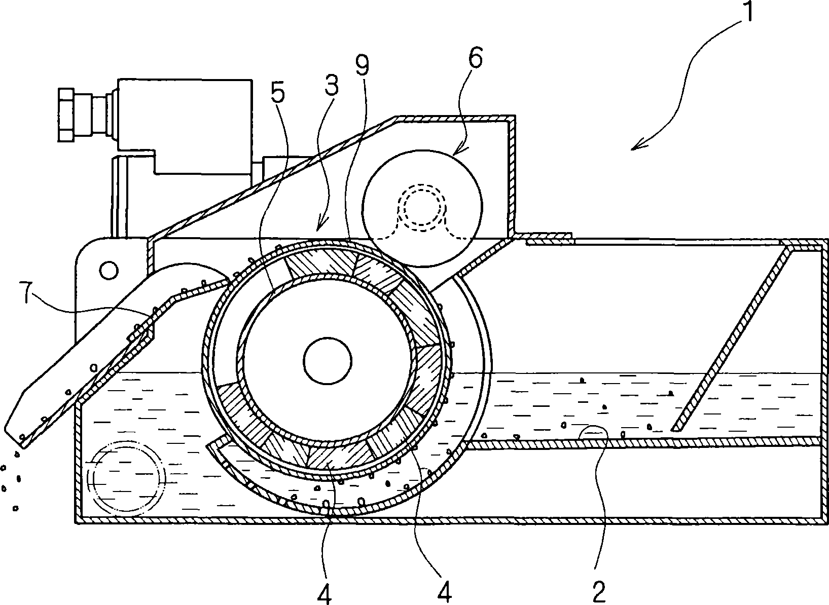
[0050] figure 1 It is a cross-sectional view showing the configuration of the rotating drum type magnetic separator according to Embodiment 1 of the present invention, taken along a plane perpendicular to the rotation axis of the rotating drum. Such as figure 1 As shown, in the rotating drum type magnetic separator of the first embodiment, a liquid storage part 2 for storing cooling liquid is provided in a box-shaped main body 1 . A rotary drum 3 is rotatably supported substantially horizontally in the vicinity of the central portion of the main body 1 so as to divide the liquid storage portion 2 into two. The rotary drum 3 is formed as a cylinder made of non-magnetic materials such as stainless steel, and an inner cylinder 5 is coaxially fixed inside the outer cylinder 9, and a plurality of magnets 4 are arranged in a predetermined arrangement on the outer peripheral surface of the inner cylinder 5. , 4, .... The polarities of the plurality of magnets 4 , 4 , .

[0051] e...

Embodiment approach 2

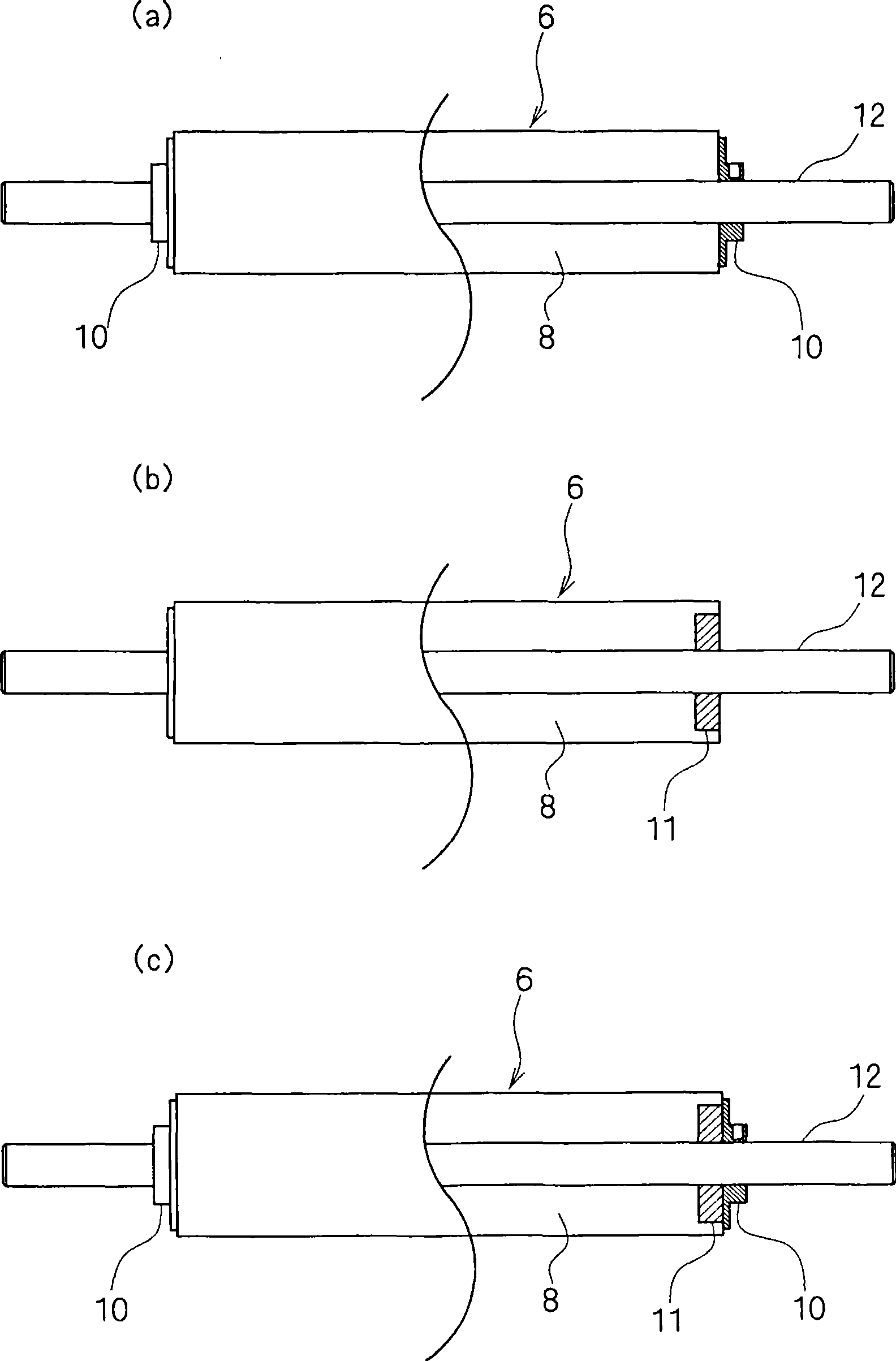
[0067] The cross-sectional view of the plane perpendicular to the direction of the rotation axis of the rotating drum showing the structure of the rotating drum type magnetic separator according to Embodiment 2 of the present invention is the same as Embodiment 1, and by giving figure 1 The same symbols are used to omit detailed description. The rotating drum type magnetic separator according to Embodiment 2 is different from Embodiment 1 in that it includes a suppressing member for suppressing the axial movement of the elastic body mounted on the surface of the pressure roller 6 .

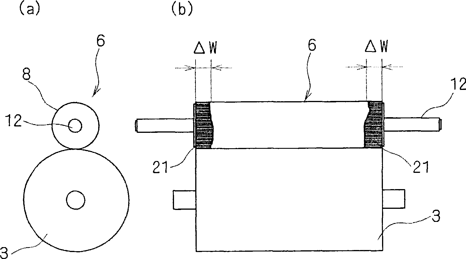
[0068] figure 2 It is a two-dimensional view showing the state of liquid leakage on the surface of the pressure roller 6 of the conventional rotary drum type magnetic separator. figure 2 (a) shows a side view of the pressing roller 6 and the rotating drum 3 of a conventional rotating drum type magnetic separator viewed from the direction of the rotating shaft, figure 2 (b) is a front view sho...

Embodiment approach 3

[0084] The cross-sectional view of the plane perpendicular to the direction of the rotation axis of the rotating drum showing the configuration of the rotating drum type magnetic separator according to Embodiment 3 of the present invention is the same as before, by giving the figure 1 The same symbols are used and detailed descriptions are omitted. The rotating drum type magnetic separator according to Embodiment 3 is characterized in that the polarities of the plurality of magnets 4 , 4 , . . . arranged on the inner cylinder 5 of the rotating drum 3 are arranged.

[0085] Fig. 4 is a sectional view and a front view showing the polarity arrangement of magnets 4, 4, ... of the rotating drum 3 of the rotating drum type magnetic separator according to Embodiment 3 of the present invention. Fig. 4 (a) shows the sectional view of the plane perpendicular to the rotation axis direction of the rotary drum 3 of the rotary drum type magnetic separator of Embodiment 3 of the present inve...


PUM


Abstract

This invention provides a rotary drum-type magnetic separator, which can satisfactorily squeeze a liquid contained in sludge without striking the sludge into the squeezing roller even when the sludge has such a shape that is likely to be striken into the squeezing roller, and a squeezing roller for use in the separator. The separator comprises a squeezing roller (6) which is abutted against a rotary drum (3) and is rotated about a shaft substantially parallel to the rotating shaft of the rotary drum (3). The rotary drum (3) has a built-in and fixed internal cylinder (5) on which a plurality of magnets (4), (4), are disposed. An external cylinder (9) formed of a nonmagnetic material is rotated on the circumference of the internal cylinder (5). An elastic body is disposed on the squeezing roller (6) in its face abutted against the rotary drum (3). The elastic body is formed of an uncrosslinked polyurethane material composed mainly of a polyester polyol. A suppressing member for suppressing the deformation of the elastic body is provided on both ends of the squeezing roller (6).

Description

technical field [0001] The present invention relates to a rotating drum type magnetic separation device for recovering fine residues (scratches) contained in cooling liquid, and a pressure roller used in the device. Background technique [0002] In the cutting and grinding of metal materials, especially magnetic materials such as iron and steel materials, cutting chips and chips discharged together with the coolant are separated from the liquid and recovered. Since chips, chips, etc. have various shapes, various magnetic separation (recovery) devices have been developed from the viewpoint of recovery efficiency. [0003] For example, since cut chips called residues are powdery, they tend to concentrate and contain liquid. Therefore, separation and recovery become difficult, so the magnetic separation device is required to have good fine residue liquid removal (liquid cutting sex) devices. [0004] As shown in Patent Document 1, in a conventional rotating drum type magnet...

Claims


Application Information

Patent Timeline
Patent Type & Authority Applications(China)
IPC IPC(8): B03C1/00B03C1/14F16C13/00
CPCB03C1/0332B03C1/247B03C2201/18B03C1/00B03C1/14F16C13/00
Inventor 宫川和彦西泽信也
Owner SUMITOMO HEAVY IND FINETECH
Why Eureka
Try Eureka