Potato production increasing method and device by treating potato seed using electron beam irradiation
An electron beam irradiation, potato technology, applied in the fields of seed and rhizome treatment, botanical equipment and methods, plant genetic improvement, etc., can solve the problem of slow effect of potato
- Summary
- Abstract
- Description
- Claims
- Application Information
AI Technical Summary
Problems solved by technology
Method used
Image
Examples
specific Embodiment approach 1
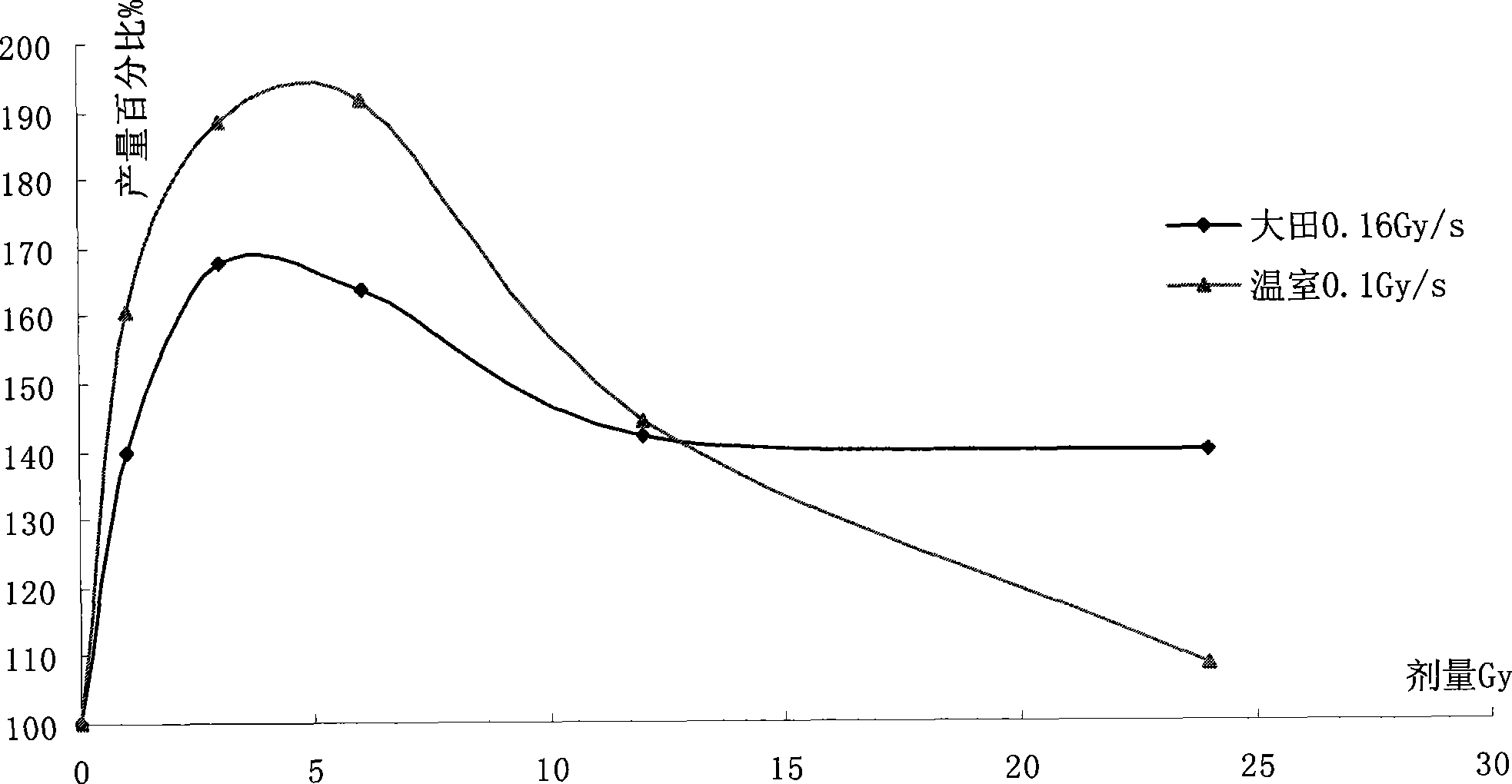
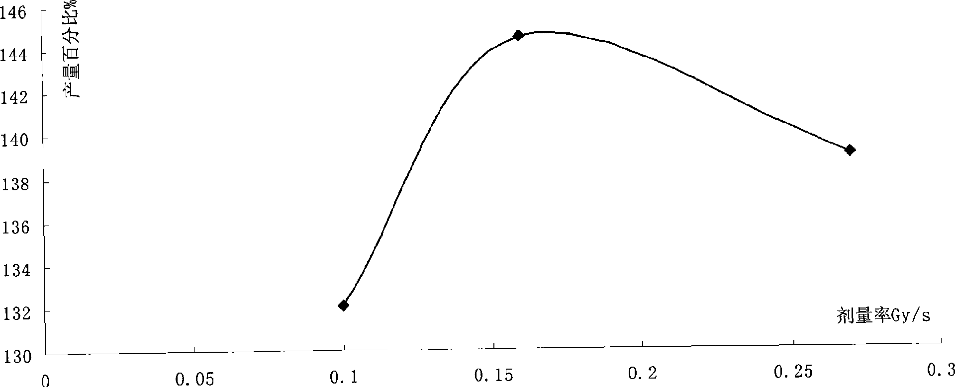
[0009] Specific embodiment one: the technical scheme of this embodiment is to irradiate seed potato with electron beam, described electron beam is the charged particle that accelerator produces, and the energy range of electron beam is between 0.5~0.9 megaelectron volts (MeV), The dose of the electron beam is 1~24 Gray (Gy); the dose rate ranges from 0.1 Gray / second (Gy / s) to 0.27 Gray / second (Gy / s), and the preferred dose rate is 0.16 Gray / second (Gy / s) ; The potato seed potato after irradiation is the seed potato for planting. The whole irradiation process was completed at room temperature. The selected potato seed potatoes are generally seed potatoes of non-defective and excellent varieties with a diameter of 0.5 cm to 3 cm.
specific Embodiment approach 2
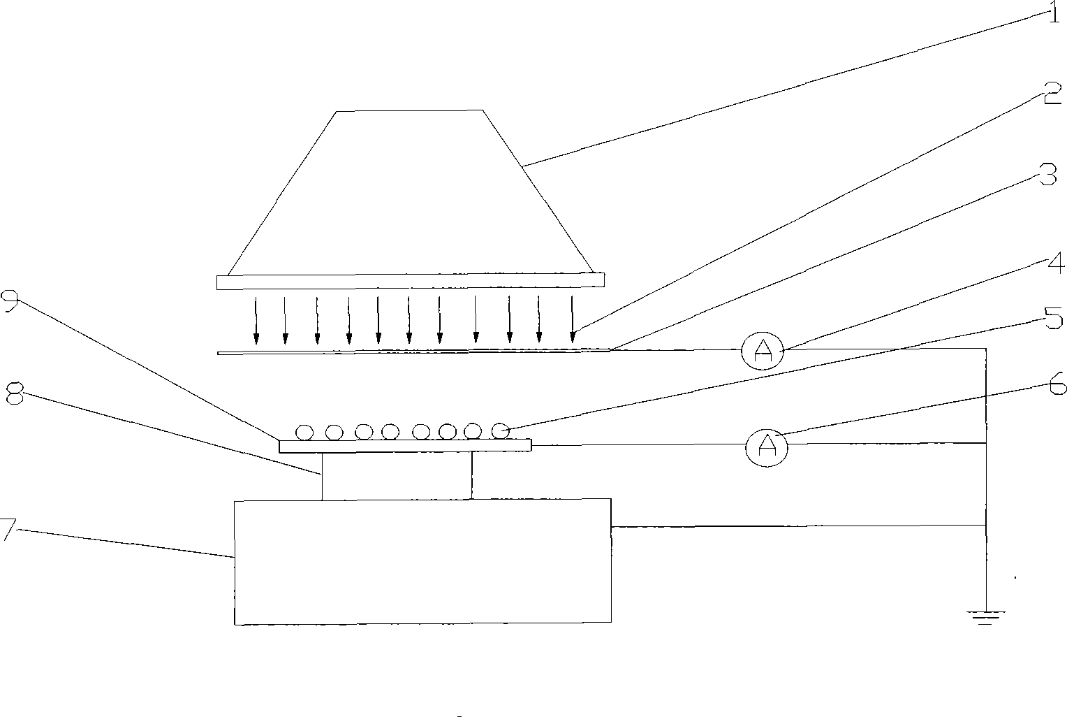
[0010] Specific implementation mode two: as figure 1 As shown, the device of the present embodiment is as follows: it comprises accelerator scanning box 1, baffle plate 3, beam meter 4, beam current integrator 6 and metal plate 9, and accelerator scanning box 1 is arranged on the top and makes the electron that it emits The beam is vertically downward, and a baffle 3 is arranged under the accelerator scanning box 1, and a metal plate 9 is arranged under the baffle 3, and both the baffle 3 and the metal plate 9 are arranged perpendicular to the electron beam emission direction and make the baffle 3 block the accelerator scanning box 1 shoot the electron beam to the metal plate 9, one end of the beam current meter 4 is connected on the baffle plate 3, one end of the beam current integrator 6 is connected on the metal plate 9, the other end of the beam current meter 4 and the beam integrator 6 The other end is grounded. Metal plate is preferably selected aluminum plate, and baff...
specific Embodiment approach 3
[0012] Specific implementation mode three: as figure 1 As shown, the difference between this embodiment and the second embodiment is that it also includes a metal bracket 7 and an insulating material body 8, the metal plate 9 is arranged on the metal bracket 7, and the insulating material body 8 is arranged between the metal plate 9 and the metal bracket 7 The two are separated between the two, and the area of the insulating material body 8 is less than the area of the special metal plate 9 so that the insulating material body 8 can not be exposed outside the metal plate 9 when vertically looking down from top to bottom.
[0013] The irradiation operation steps of this embodiment are as follows: the first step, debug the electron beam energy of the accelerator scanning box 1 under blank conditions, such as debugging to 0.8MeV; debug the intensity of the electron beam 2 with the beam current meter 4 connected to the baffle plate 3 (i.e. dose rate). In the second step, the ...
PUM
 Abstract
Description
Claims
Application Information
 - R&D
- Intellectual Property
- Life Sciences
- Materials
- Tech Scout
- Unparalleled Data Quality
- Higher Quality Content
- 60% Fewer Hallucinations
Browse by: Latest US Patents, China's latest patents, Technical Efficacy Thesaurus, Application Domain, Technology Topic, Popular Technical Reports.
© 2025 PatSnap. All rights reserved.Legal|Privacy policy|Modern Slavery Act Transparency Statement|Sitemap|About US| Contact US: help@patsnap.com


