Stirring transfer car and stirring drum control device

A mixing transport vehicle and control device technology, which is applied in the direction of control devices, cement mixing devices, clay preparation devices, etc., can solve problems such as the inability to realize the constant speed function of the mixing drum, and achieve the effect of meeting the control requirements

Inactive Publication Date: 2009-06-10
河北雷萨重型工程机械有限责任公司
View PDF0 Cites 27 Cited by
  • Summary
  • Abstract
  • Description
  • Claims
  • Application Information

AI Technical Summary

Problems solved by technology

[0008] When driving, the speed of the oil pump n 1 That is, the rotational speed of the engine changes at any time, and the displacement q of the quantitative motor 2 is a certain value, since the operating handle is placed in the agitation gear, the swing angle of the oil pump variable rod is fixed, so the displacement q of the oil pump 1 is also a certain value, then when the engine speed changes, the speed n of the oil pump 1 It also changes accordingly, and the speed n of the hydraulic motor can be known from the formula 2 will change with the motor speed n 2 The speed ratio between the rotating speed of the mixing drum and the rotating speed of the mixing drum is i=6.94, the rotating speed of the mixing drum will also change with the change of the engine speed, and the constant rotating speed function of the mixing drum cannot be realized

Method used


Image

  • Stirring transfer car and stirring drum control device
  • Stirring transfer car and stirring drum control device
  • Stirring transfer car and stirring drum control device

Examples


Embodiment Construction

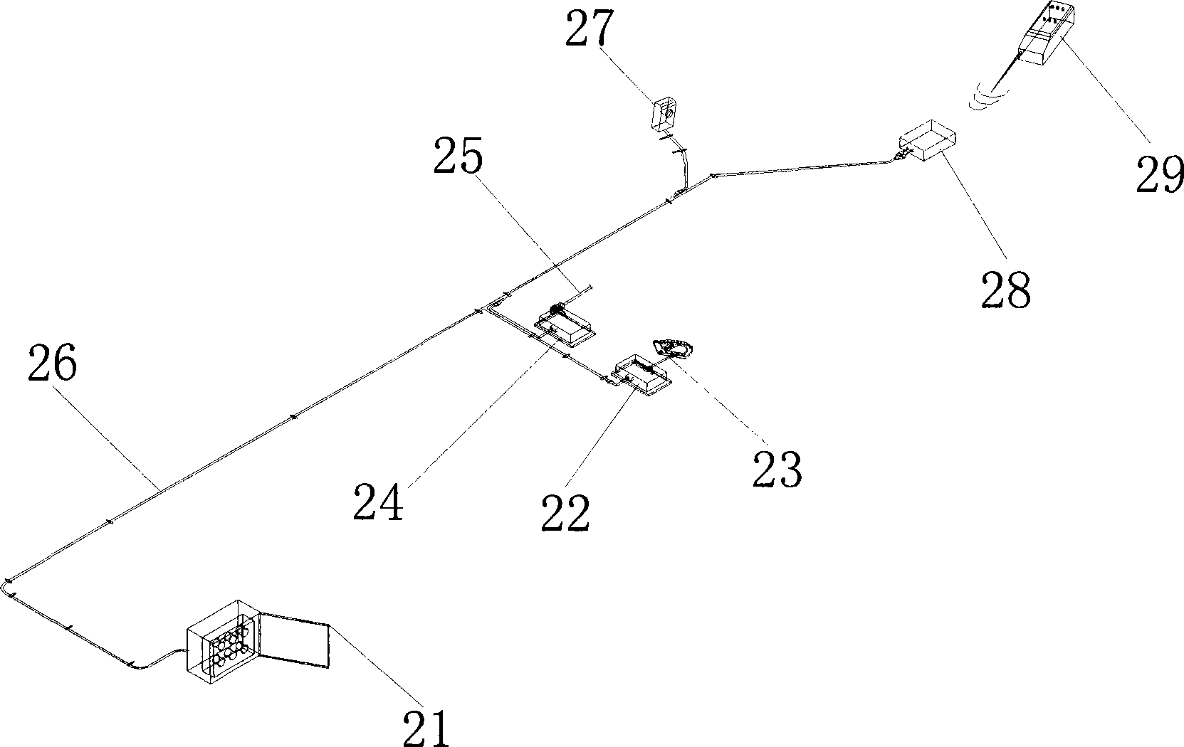
[0072] Please refer to figure 2 , is a schematic diagram of the composition of the electronic control operating system of the present invention, as shown in the figure, the electronic control operating system is mainly composed of a close control cabinet 21, an oil pump actuator 22, an oil pump variable lever 23, an accelerator actuator 24, an accelerator cable 25, and a control wire harness 26 , speed sensor 27, remote controller 29, controller 28, etc., its main function is to control the rotation angle of the oil pump actuator 22 and the throttle actuator 24 pull rod through the electronic controller to control the rotation angle of the mixing drum in forward, reverse, middle Position stop and engine acceleration and deceleration functions, so as to complete the feeding, stopping and discharging functions of the mixer truck, and through advanced microcomputer technology, sampling the speed pulse of the hydraulic motor, and constantly adjusting the rotation angle of the 22 p...


PUM


Abstract

The invention discloses an agitator transporting truck and an agitating drum control device thereof. The agitating drum control device comprises an operation controller, an electronic controller, an oil pump actuator, an accelerograph actuator, and a rotation speed sensor, wherein the electronic controller is electrically connected with the operation controller to control the operation of an agitating drum of the agitator transporting truck according to an operation command of the operation controller; moreover, the electronic controller also controls the agitating drum to rotate at a constant speed during the running of the agitator transporting truck; the oil pump actuator is electrically connected with the electronic controller to control the working position of the agitating drum according to an operation command of the electronic controller; the accelerograph actuator is electrically connected with the electronic controller to control the rotation speed of an engine of the agitator transporting truck according to an operation command of the electronic controller; and the rotation speed sensor is electrically connected with the electronic controller to detect the rotation speed of the agitating drum and feed back a rotation speed pulse signal of the agitating drum to the electronic controller. The agitating drum control device has two operation modes, namely, remote control and close control, and has constant speed control, convenient installation, simple operation and lower cost.

Description

technical field [0001] The invention belongs to a stirring transport machine, in particular to a stirring transport vehicle which adopts a mechanical oil pump to control a stirring drum and an electronic control device thereof. Background technique [0002] At present, in the commonly used mixer trucks on the market, the device for controlling the rotating speed of the mixing drum generally adopts an electronically controlled oil pump type and a mechanical oil pump type. The former has higher equipment cost, while the latter has a lower cost of mechanical oil pump, but there is no better electronic control product in terms of automatic control. [0003] For the mechanical oil pump control device, the mixer control system currently uses a mechanical linkage structure, such as figure 1 As shown, it is mainly composed of oil pump variable rod 11, cab control flexible shaft 12, throttle control rod 13, oil pump control push-pull rod 14, control handle 15, indoor control 16, pos...

Claims


Application Information

Patent Timeline
Patent Type & Authority Applications(China)
IPC IPC(8): B28C7/02B28C5/42
Inventor 詹振京梁文蓉韩万喜杨琴李殿浦
Owner 河北雷萨重型工程机械有限责任公司
Why Eureka
Try Eureka