
Motor push rod type power-assisted steering apparatus

An electric power steering and electric push rod technology, applied in the field of auto parts, can solve problems such as the inability to adjust and control the power assist characteristics in real time, the difficulty in coordinating the lightness of low-speed steering, and the increase in the size of the steering gear, so as to shorten the production and development cycle, High degree of assembly automation and the effect of reducing disturbance

Active Publication Date: 2012-11-28
BEIJING AUTONICS TECH
View PDF0 Cites 0 Cited by
  • Summary
  • Abstract
  • Description
  • Claims
  • Application Information

AI Technical Summary

Problems solved by technology

Traditional hydraulic power steering has the following problems: the power assist characteristics cannot be adjusted and controlled in real time with the vehicle speed, and it is difficult to coordinate the contradiction between the lightness of low-speed steering and the "road feel" of high-speed steering; even if the steering is not turned, the oil pump is always working, and there is a parasitic loss of energy; Due to the oil leakage and maintenance problems of the hydraulic system itself, the maintenance cost is increased, and the hydraulic oil will also pollute the environment
Recirculating ball electric power steering is mainly used in commercial vehicles. When the front axle load of commercial vehicles is large, if the motor and power-assisted mechanical device are directly installed on the steering gear, the size of the steering gear will increase, resulting in bulkiness and A series of problems such as inconvenient installation

Method used


Image

  • Motor push rod type power-assisted steering apparatus
  • Motor push rod type power-assisted steering apparatus
  • Motor push rod type power-assisted steering apparatus

Examples


Embodiment Construction

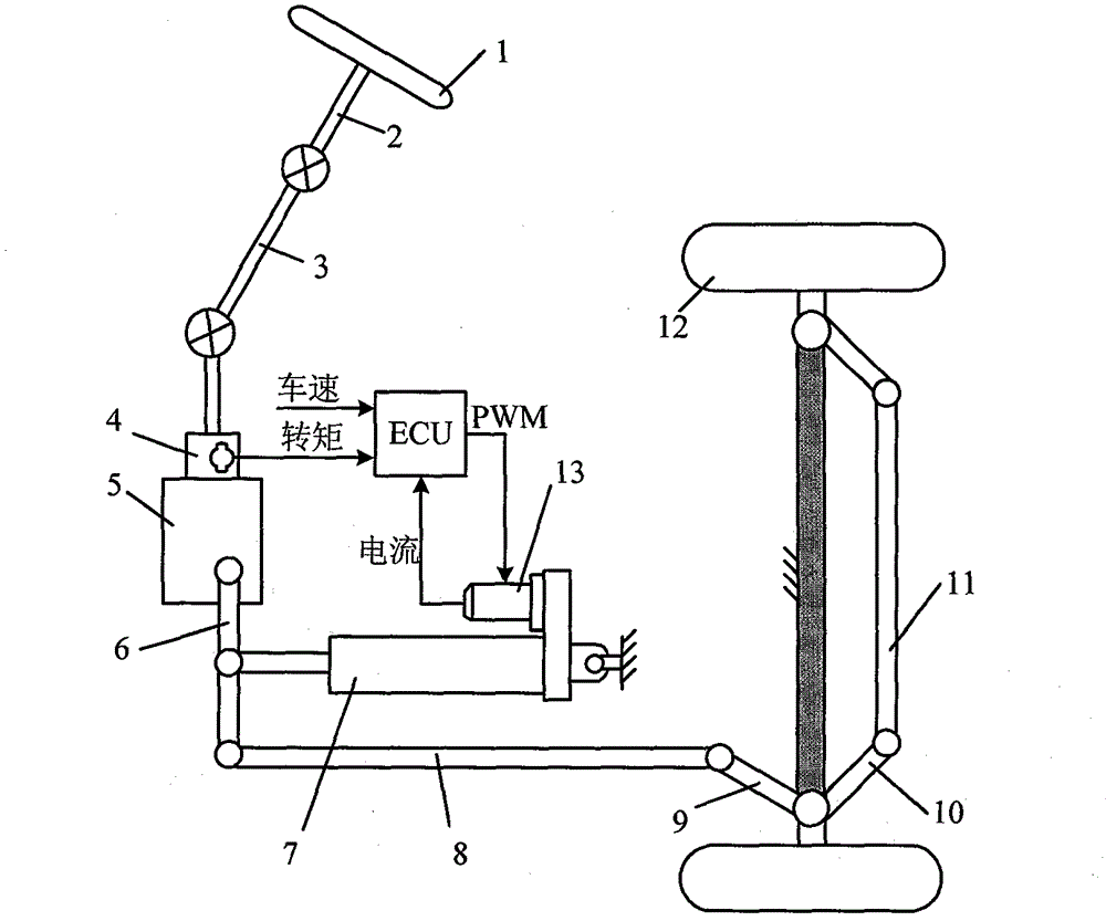
[0024] Such as figure 1 As shown, the electronic control unit according to the collected steering wheel torque T s Determine the target current Icmd of the booster motor with the vehicle speed V, and then perform feedback tracking control on the booster motor current according to the actual current I and target current Icmd of the booster motor.

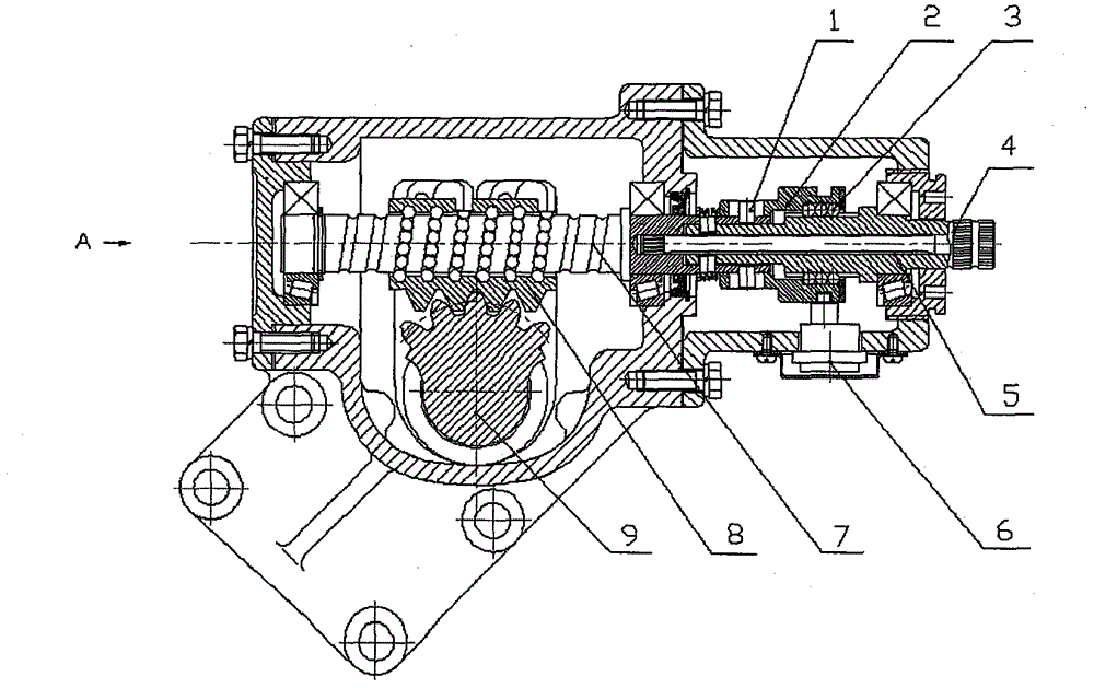
[0025] Such as figure 2 As shown, the working principle of the electric push rod type electric power steering device is: when the driver turns the steering wheel 1, the driver's torque is transmitted to the input shaft of the recirculating ball steering gear 5 through the steering shaft 2 and the steering transmission shaft 3, and then The input shaft of the recirculating ball steering gear 5 is provided with a torque measuring device 4, and the torque measuring device 4 sends the measured torque of the driver to the electronic control unit ECU, and the ECU controls the electric push rod according to the torque signal and combined ...


PUM


Abstract

The invention relates to an electrical push rod type electrical power-assisted steering device, which comprises a recirculating ball steering gear provided with a torque sensing device, an electrical push rod and an electronic control unit, wherein the torque sensing device is used for detecting moment acted on a steering wheel, and is arranged on an input shaft of the recirculating ball steering gear. One end of the electrical push rod is connected with a steering rock arm, and the other end of the electrical push rod is connected with a vehicle frame. The electrical push rod comprises a power-assisted motor and a speed reducing mechanism, a push rod and so on. An input shaft of the speed reducing mechanism of the power-assisted motor is connected with an output shaft of the power-assisted motor, an output shaft of the speed reducing mechanism is connected with a screw rod of the push rod, and the moment output by the power-assisted motor pushes a rock arm shaft to rotate through a screw nut transmission pair. The electronic control unit is used for controlling the current of the power-assisted motor according to signals of the torque of the steering wheel and the vehicle speed and so on. The steering device can save energy, provide proper power assistance under various running work conditions, has fewer parts, light weight, compact structure and high assembly automatic degree, and is a steering mechanism of vehicle power with energy conservation, safety and environmental protection.

Description

Technical field [0001] The invention belongs to the technical field of automobile parts, and in particular relates to an electric push rod type recirculating ball electric power steering device for vehicles. Background technique [0002] At present, the steering gear for vehicles is mainly divided into two types: rack and pinion type and recirculating ball type. Among them, the rack and pinion type steering gear is mainly used for passenger cars, and the recirculating ball type steering gear is mainly used for commercial vehicles. Traditional power steering is hydraulic power steering, and the amount of power assistance is controlled by a slide valve or a rotary valve. Traditional hydraulic power steering has the following problems: the power assist characteristics cannot be adjusted and controlled in real time with the vehicle speed, and it is difficult to coordinate the contradiction between the lightness of low-speed steering and the "road feel" of high-speed steering; ev...

Claims


Application Information

Patent Timeline
Patent Type & Authority Patents(China)
IPC IPC(8): B62D5/04
Inventor 施国标杨丽鑫赵万忠孙逢春林程周珑
Owner BEIJING AUTONICS TECH
Learn More