D trigger for resonance tunnel-through diode

A technology of resonant tunneling and diodes, which can be used in pulse generation, electrical components, and electrical pulse generation. It can solve problems such as application limitations and increasing circuit complexity.

Inactive Publication Date: 2009-06-10
INST OF SEMICONDUCTORS - CHINESE ACAD OF SCI
View PDF0 Cites 4 Cited by
  • Summary
  • Abstract
  • Description
  • Claims
  • Application Information

AI Technical Summary

Problems solved by technology

However, there is no standard D flip-flop designed by using resonant tunneling diodes, and then cascaded for frequency division. The existing resonant tunneling diode frequency dividers are often limited in their application, such as the input clock signal must meet specific requirements. , such as delay, duty cycle, etc., so it may be necessary to integrate a clock buffer unit in the circuit,
[0007] This undoubtedly increases the complexity of the circuit, contradicting the original intention of the design

Method used


Image

  • D trigger for resonance tunnel-through diode
  • D trigger for resonance tunnel-through diode
  • D trigger for resonance tunnel-through diode

Examples


Embodiment Construction

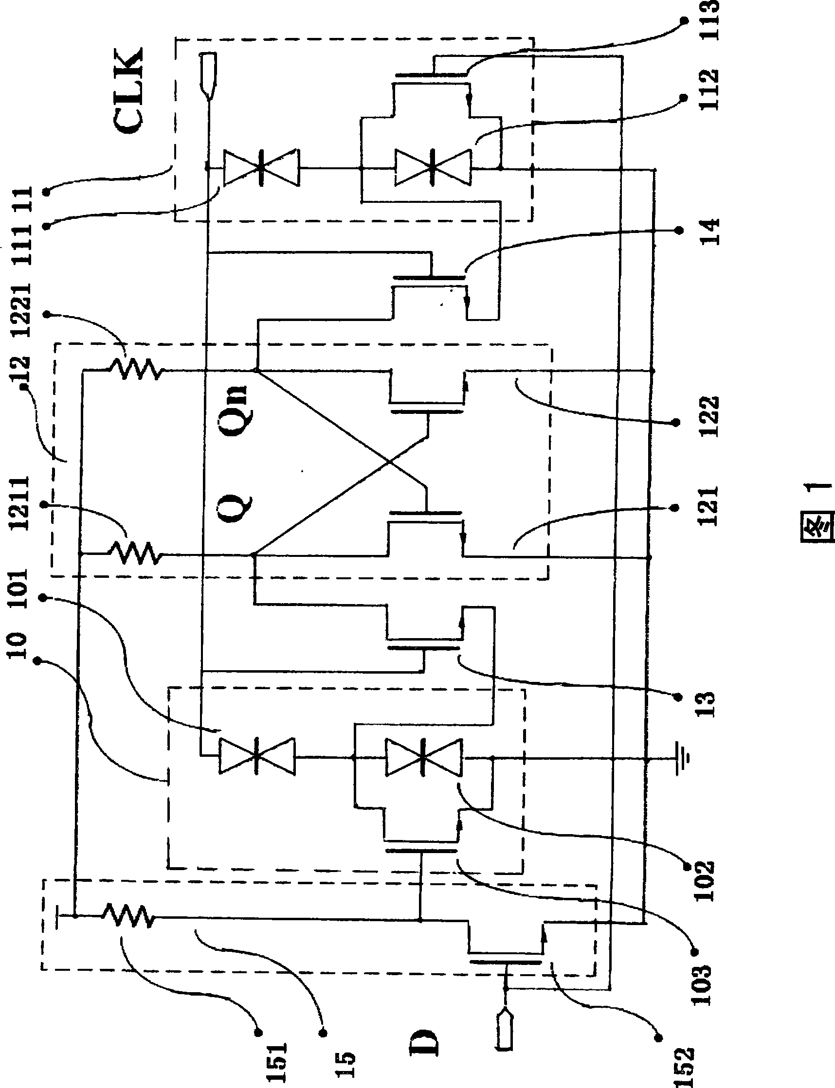
[0045]Please refer to Figure 1, which shows the structure of the first embodiment of the resonant tunneling diode D flip-flop: the circuit uses a single DC power supply, inputs data signal D and clock signal CLK, and outputs a pair of complementary data signals Q, Qn .

[0046] Please refer to FIG. 1, which shows that the data signal D is connected to the gate of field effect transistor 152, and field effect transistor 152 is used for inverting the input signal, and its structure is a standard E / R inverter; The drain is connected to the pull-up resistor 151 , the other end of the pull-up resistor 151 is connected, the input signal is applied to the gate of the field effect transistor 152 , and the inverted signal is output from the drain of the field effect transistor 152 .

[0047] Please refer to FIG. 1, wherein the first monostable-bistable conversion logic unit 10 includes: two resonant tunneling diodes 101, 102 and a field effect transistor 103, the two resonant tunneling...


PUM


Abstract

The invention relates to a resonance tunneling dioxide D trigger, which comprises a first monostability-bistability conversion logic unit, a second monostability-bistability conversion logic unit, a latch unit, a transmission gate, a second transmission gate and a phase inverter, wherein the latch unit consists of a first phase inverter and a second phase inverter; the output of the first phase inverter is connected with the input end of the second phase inverter; the output of the second phase inverter is connected with the input end of the first phase inverter; the input end of the first transmission gate is connected with the output end of the first monostability-bistability conversion logic unit, while the output end is connected to the input end of the latch unit; the input end of the second transmission gate is connected with the output end of the second monostability-bistability conversion logic unit, while the output end is connected with the input end of the latch unit; and the output end of the phase inverter is connected with the input end of the first monostability-bistability conversion logic unit, one end of the phase inverter is earthed, and the input end of the phase inverter is connected to the input end of the second monostability-bistability conversion logic unit.

Description

technical field [0001] The present invention relates to a flip-flop circuit, in particular to a three-dimensional integration process suitable for using semiconductors, especially compound semiconductors, which utilizes the highly non-linear DC characteristics of resonant tunneling diodes to simplify circuit structure complexity A resonant tunneling diode D flip-flop suitable for high-frequency applications realized by advanced technology. Background technique [0002] Resonant tunneling diode is a nanoelectronic device based on quantum tunneling effect, and it is also one of the fastest solid-state electronic devices working at room temperature. [0003] However, since the resonant tunneling diode is a two-terminal device, current modulation cannot be realized, so integration with a three-terminal device is common in applications. The most integrated device with the resonant tunneling diode in the actual circuit is the high electron mobility transistor, and the circuit for...

Claims


Application Information

Patent Timeline
Patent Type & Authority Applications(China)
IPC IPC(8): H03K3/037H03K3/315
Inventor 杜睿杨富华
Owner INST OF SEMICONDUCTORS - CHINESE ACAD OF SCI
Why Eureka
Try Eureka