Apparatus and method for controlling DC bias of radio frequency discharge system

A technology of DC bias voltage and radio frequency power supply, which is applied to the components, circuits, amplifiers, etc. of the amplifying device, and can solve the practical requirements that it is difficult to re-convert, unable to meet the flexible conversion and flexible selection of power control method and voltage control method, etc. problem, to achieve an effect that is conducive to operation

Active Publication Date: 2009-06-10
BEIJING NAURA MICROELECTRONICS EQUIP CO LTD
View PDF0 Cites 3 Cited by
  • Summary
  • Abstract
  • Description
  • Claims
  • Application Information

AI Technical Summary

Problems solved by technology

At this point, since the entire process flow is based on figure 2 shown to control the DC bias, it is difficult to reconvert to the figure 1 The device shown to control the DC bias is performed on the
It can be seen that the existing technology is still unable to meet the actual requirements of flexible conversion and flexible selection between the power control method and the voltage control method

Method used


Image

  • Apparatus and method for controlling DC bias of radio frequency discharge system
  • Apparatus and method for controlling DC bias of radio frequency discharge system
  • Apparatus and method for controlling DC bias of radio frequency discharge system

Examples


Embodiment Construction

[0060] In order to make the purpose, technical solution and advantages of the present invention clearer, the present invention will be further described in detail below in conjunction with the accompanying drawings and specific embodiments.

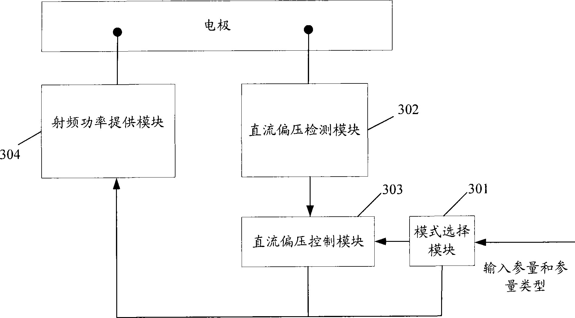
[0061] image 3 It is a schematic diagram of the device for controlling the DC bias voltage of the radio frequency discharge system according to the present invention. Such as image 3 As shown, the device may include: a mode selection module 301 , a DC bias voltage detection module 302 , a DC bias voltage control module 303 and a radio frequency power supply module 304 . in,

[0062] The mode selection module 301 is used to receive input information including a parameter and a parameter type; determine the type of the parameter, and if the parameter type is a power-related type, then output the parameter as a power-related characteristic parameter to the radio frequency power supply module 304; if If the parameter type is a voltage-re...


PUM


Abstract

The present invention relates to a device and a method for controlling direct current bias voltage of a radio-frequency discharge system. The system comprises a direct current bias voltage detecting module, a mode selecting module, a direct current bias voltage controlling module and a radio-frequency power providing module, wherein the mode selecting module is used for receiving parameters and parameter types. If the parameter type is the type which represents voltage, then the direct current bias voltage controlling module computes a power value according to relevant characterization parameters of the voltage and a detected direct current value, and the radio-frequency power providing module provides power according to the computed power value. If the parameter type is the type which represents the power, then the radio-frequency power providing module provides the power according to the relevant characterization parameters of the power. When applying the proposal of the present invention, the mode selecting module can utilize a result which judges the types of the parameters to determine to carry out a power controlling method or a voltage controlling method, so that the two different direct current bias voltage controlling methods can be flexibly selected so as to achieve the compatible aim and be more favorable for the operation of process operators.

Description

technical field [0001] The invention relates to the technical field of plasma etching, in particular to a device and method for controlling a DC bias voltage of a radio frequency discharge system. Background technique [0002] Plasma etching technology is one of the key processes in integrated circuit manufacturing, and its purpose is to copy the mask pattern onto the wafer surface. The principle of plasma etching technology is roughly: under low pressure, the reactive gas is ionized under the excitation of radio frequency power and forms plasma. The plasma can form a DC bias voltage with the wafer surface placed on the lower electrode, and this DC bias voltage will attract positively charged ions and active reactive groups in the plasma to accelerate the bombardment of the wafer surface, thereby accelerating the chemical reaction of the wafer surface. reaction to increase the etch rate. The DC bias described here is also commonly referred to as DC self-bias. [0003] The...

Claims


Application Information

Patent Timeline
Patent Type & Authority Applications(China)
IPC IPC(8): H05H1/46H01L21/00H01L21/3065
CPCH03F1/0211H03F1/0277H03F3/20
Inventor 赵祎刘利坚
Owner BEIJING NAURA MICROELECTRONICS EQUIP CO LTD
Why Eureka
Try Eureka