Antenna input tuning circuit

A technology for tuning circuits and antenna input, which is used in the adjustment of resonant circuits, discontinuous tuning with variable adjustment elements, electrical components, etc. more problems

Inactive Publication Date: 2009-06-10
NEURO SOLUTION CORP
View PDF0 Cites 6 Cited by
  • Summary
  • Abstract
  • Description
  • Claims
  • Application Information

AI Technical Summary

Problems solved by technology

[0013] However, when a digitally tuned radio receiver is converted into an IC, the varactor diodes and coils of the VCO constituting the antenna input tuning circuit 103 and the local oscillation circuit 104 cannot be converted into an IC, and have to be used as external parts of the IC.
In this way, conventional digital radio receivers have the problem of increasing the number of external parts and increasing the cost when they are integrated into ICs.

Method used


Image

  • Antenna input tuning circuit
  • Antenna input tuning circuit
  • Antenna input tuning circuit

Examples


Embodiment Construction

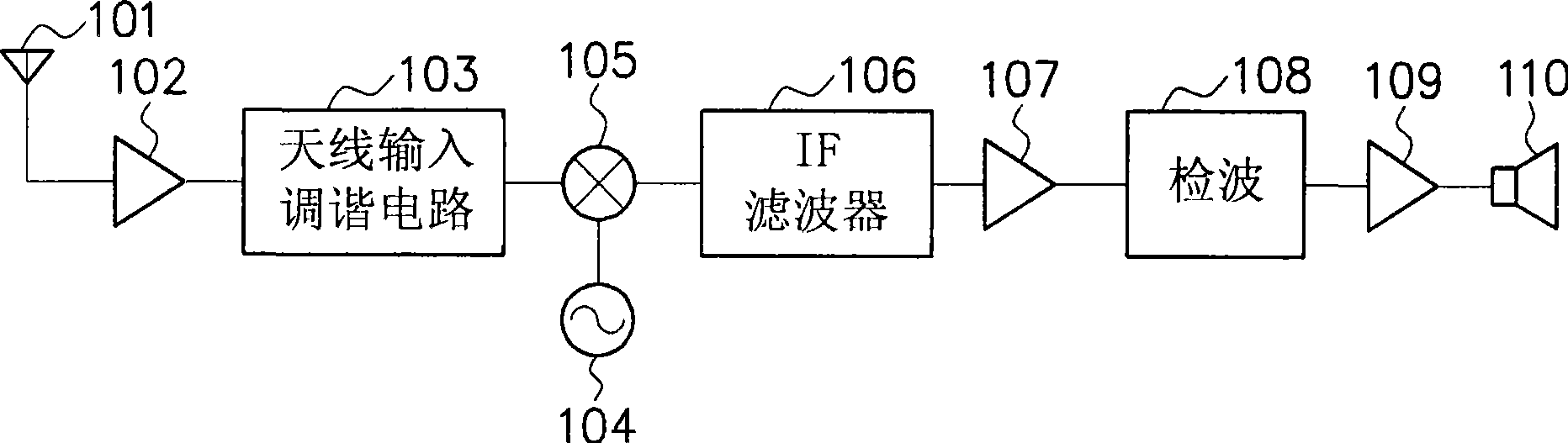
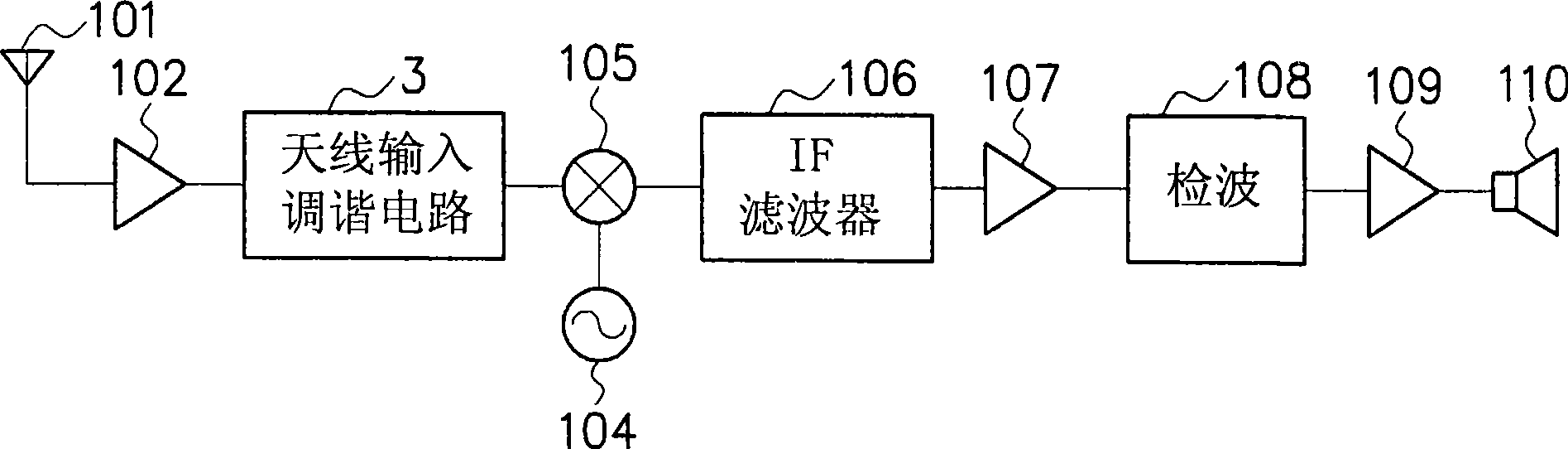
[0030] Next, an embodiment of the present invention will be described based on the drawings. figure 2 A configuration example of a radio receiver to which the antenna input tuning circuit of this embodiment is applied is shown. in the figure 2 , for those with figure 1 The constituent elements having the same function as the shown constituent elements are marked with the same symbols. figure 2 The constituent elements shown (except for the antenna 101, the audio amplifier circuit 109, and the speaker 110) are integrated on one semiconductor chip by, for example, CMOS (Complementary Metal Oxide Semiconductor) processing.

[0031] exist figure 2 Among them, the antenna 101 is used to receive radio waves to obtain a weak high frequency signal (RF signal). After the high frequency signal is amplified by the high frequency amplifier circuit 102, in order to improve the noise figure and interference characteristics, the antenna input tuning circuit 3Select a frequency. The ...


PUM


Abstract

An antenna input tuning circuit comprising a variable tuning filter (11) for making the tuning frequency fF variable by selecting any one of resistor elements through switching, and an oscillation circuit (12) constituted similarly to the variable tuning filter (11), wherein the oscillation frequency fL of the oscillation circuit (12) monitored by a frequency counter (13) is compared with a desired receiving frequency fr preset by a control circuit (14) based on respective frequency counts, oscillation frequency fL of the oscillation circuit (12) is varied such that the both frequencies coincide within an allowable error range and then the tuning frequency fF of the variable tuning filter (11) is varied correspondingly, thus regulating the tuning frequency fF of the variable tuning filter (11) to coincide with the desired receiving frequency fr without using a variable capacitance diode or the like hard to go IC-based.

Description

technical field [0001] The present invention relates to an antenna input tuning circuit, in particular, an antenna input tuning circuit suitable for performing frequency selection of a high-frequency signal obtained by receiving broadcast waves with an antenna. Background technique [0002] Typically, radio receivers such as figure 1 constitute like that. That is, antenna 101 receives broadcast waves to obtain weak high-frequency signal (RF signal). After the high-frequency signal is amplified in high-frequency amplifier circuit 102, a frequency is selected in antenna input tuning circuit 103 in order to improve noise figure and interference characteristics. The output signal of the antenna input tuning circuit 103 is mixed with the local oscillation signal generated from the local oscillation circuit 104 in a mixer circuit 105, and the frequency is converted into an intermediate frequency signal (IF signal). [0003] The intermediate frequency signal output from the mixin...

Claims


Application Information

Patent Timeline
Patent Type & Authority Applications(China)
IPC IPC(8): H04B1/18H04B1/26H03J5/02
CPCH03J2200/06H03L7/0805H03H11/1252H04B1/18H03H11/1291H03J2200/18H03L7/08H03J2200/10
Inventor 池田毅宫城弘
Owner NEURO SOLUTION CORP
Why Eureka
Try Eureka