Slide transverse type symmetrical loading structure

A horizontal and symmetrical technology, applied in the direction of measuring devices, mechanical devices, instruments, etc., can solve the problems of inconvenient installation of samples, unstable test process, etc., achieve uniform stress distribution, simplify structure and control system, and reduce manufacturing costs. Effect

Inactive Publication Date: 2009-06-17
INST OF ROCK AND SOIL MECHANICS - CHINESE ACAD OF SCI
View PDF0 Cites 26 Cited by
  • Summary
  • Abstract
  • Description
  • Claims
  • Application Information

AI Technical Summary

Problems solved by technology

[0008] In view of the above-mentioned defects in the existing rock true triaxial system loading structure, the purpose of the present invention is to provide a sliding horizontal symmetrical loading structure for the rock true triaxial test system, which can inherit the Motegi type true triaxial system The advantages of the loading structure, and overcome the inconvenience of sample installation and the instability of the test process caused by the vertical sliding frame, and the installation and expansion of the sensor are convenient, and can realize the direct observation of the sample loading process without oil pressure

Method used


Image

  • Slide transverse type symmetrical loading structure
  • Slide transverse type symmetrical loading structure
  • Slide transverse type symmetrical loading structure

Examples


Embodiment Construction

[0031] Below in conjunction with accompanying drawing, the present invention will be further described:

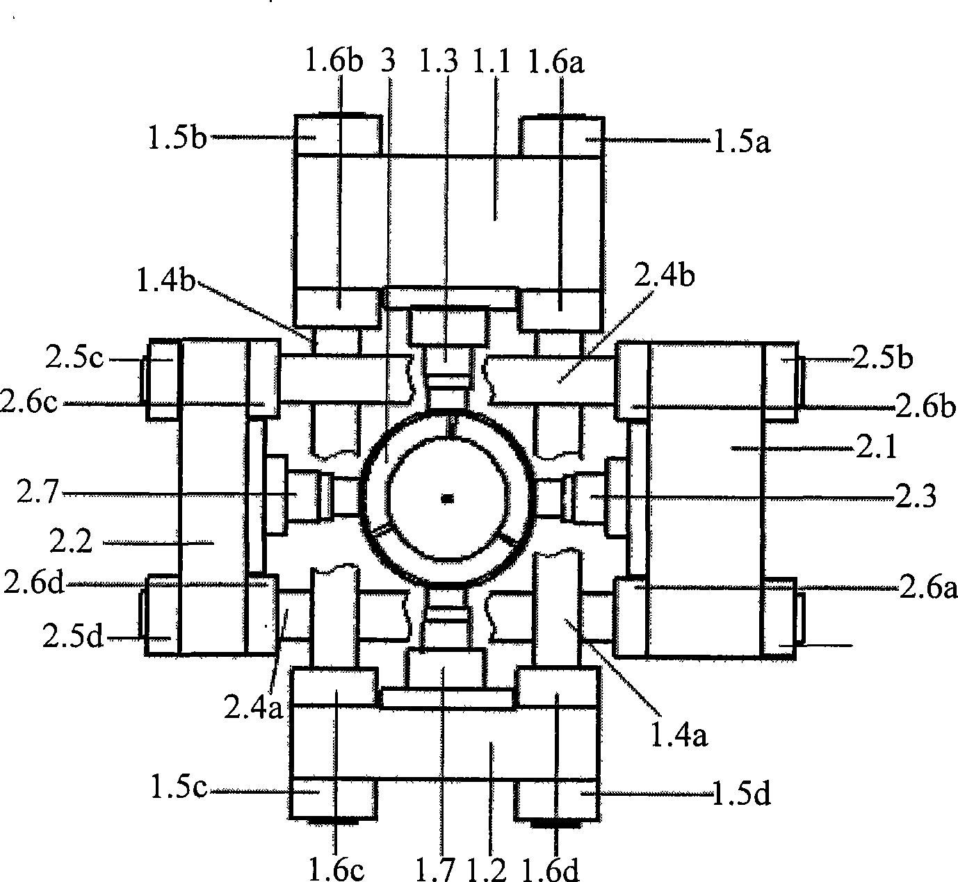
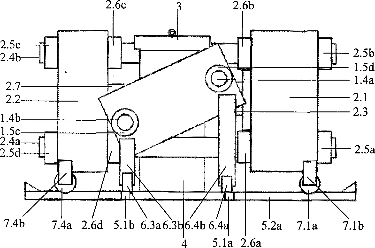
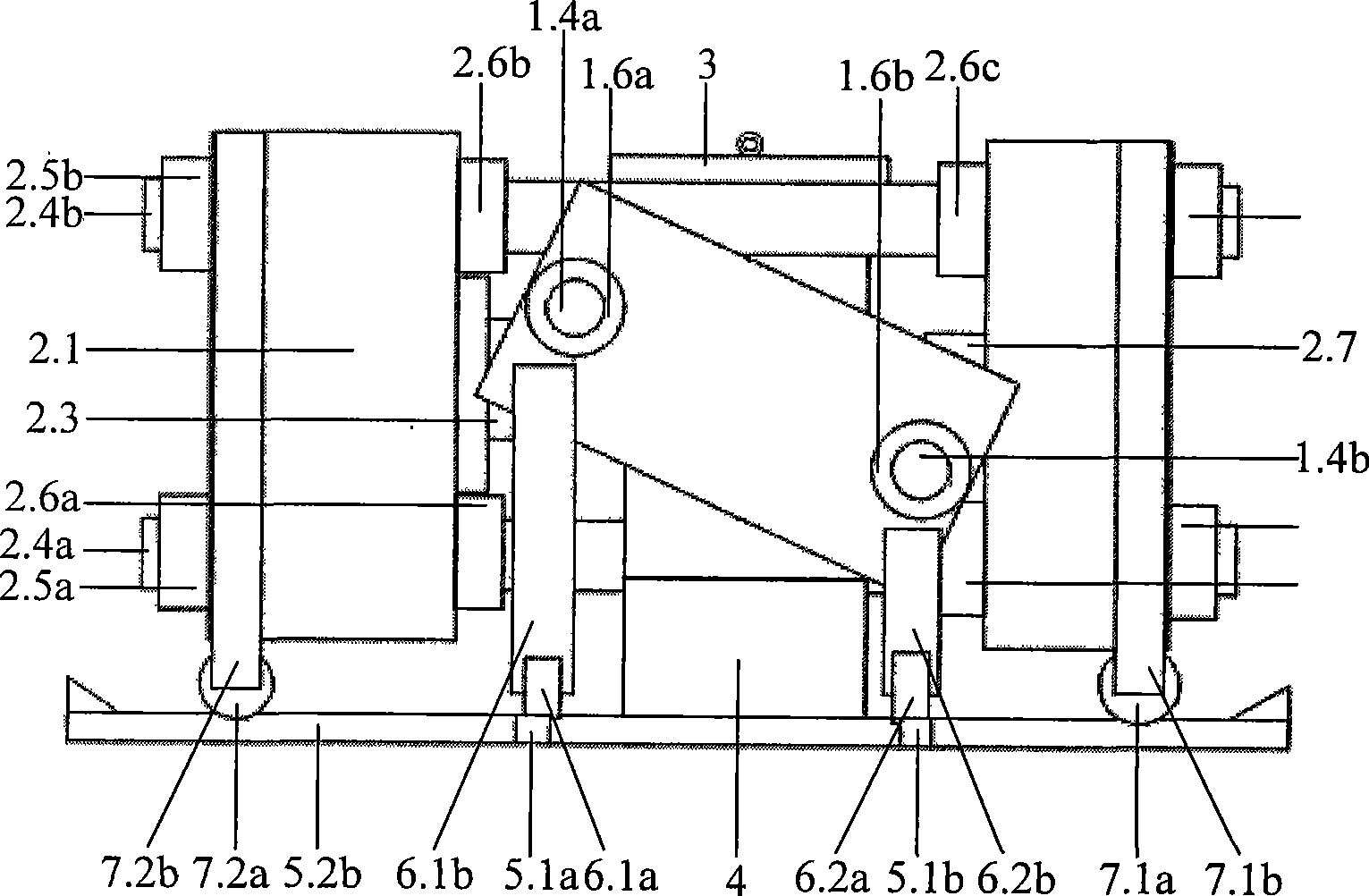
[0032] Such as figure 1 , 2 Shown in and 3, sliding frame one 1 comprises main frame beam 1.1, sub-frame beam 1.2, hydraulic jack 1.3, frame beam 1.4, outer lock nut 1.5, inner lock nut 1.6 and reaction seat 1.7. The frame beam 1.4 is connected with the main frame beam 1.1 and the sub-frame beam 1.2, and the outer lock nut 1.5 and the inner lock nut 1.6 fix the frame beam 1.4, the main frame beam 1.1 and the sub-frame beam 1.2; the hydraulic jack 1.3 and the reaction force Seat 1.7 is respectively placed in the inner side of main frame beam 1.1 and auxiliary frame beam 1.2.

[0033] Such as figure 1 , 2 Shown in and 3, sliding frame two 2 comprises main frame beam 2.1, subframe beam 2.2, hydraulic jack 2.3, frame beam 2.4, outer lock nut 2.5, inner lock nut 2.6 and reaction seat 2.7. The frame beam 2.4 is connected with the main frame beam 2.1 and the sub-frame beam 2...


PUM

PropertyMeasurementUnit
angleaaaaaaaaaa

Abstract

The invention discloses a transverse sliding symmetrical loading structure which essentially consists of two sliding frames, a true triaxial pressure chamber, two groups of supports and two groups of slideways in the shape of an intersecting parallel. The two sliding frames are orthogonally and transversely arranged, on each of which is sequentially fixed with a main frame transom, a subframe transom, a pair of frame transverse columns, four pairs of cage nuts, a hydraulic jack and a counterforce base. The frame transverse columns are connected with the main frame transom and the subframe transom, external cage nuts and internal cage nuts fix the frame transverse columns, the main frame transom and the subframe transom, and the hydraulic jack and the counterforce base are respectively arranged inside the main frame transom and the subframe transom; the true triaxial pressure chamber is arranged in the center of the two sliding frames; the two sliding frames are arranged in the slideways through a group of corresponding supports and can freely move within a certain range. The structure can ensure the internal stress to be uniformly distributed in the test sample during loading, and has the advantages of convenient test sample loading and unloading, simple structure and relative low cost.

Description

technical field [0001] The invention relates to a sliding horizontal symmetrical loading structure, which can be used as the basic structure of the loading part of the rock true triaxial test system. Background technique [0002] The main purpose of rock mechanics test is to simulate the mechanical behavior of rock under natural stress state. As we all know, the natural rock mass, especially under the action of tectonic stress, often has different stresses in three directions, and the current conventional triaxial test can only simulate the behavior of cylindrical samples with equal intermediate principal stress and minimum principal stress. mechanical properties. To simulate the mechanical properties of rock under triaxial stress conditions, a true triaxial testing system (True triaxial testing system: TTS) was used. Most of the rock samples in the true triaxial test are cuboids (or cubes) with 6 faces, which can be subjected to different uniform pressure loads in three d...

Claims


Application Information

Patent Timeline
Patent Type & Authority Applications(China)
IPC IPC(8): G01N3/00G01N19/00G01N33/24
Inventor 李小春石露冯夏庭
Owner INST OF ROCK AND SOIL MECHANICS - CHINESE ACAD OF SCI
Why Eureka
Try Eureka