Electric relay having life memory function and apparatus thereof

A technology for relays and electronic devices, applied in the directions of relays, circuit devices, electromagnetic relays, etc., can solve the problems of no setting to warn, inform users, open circuit or short circuit, burnout, etc.

Inactive Publication Date: 2009-06-17
MOXA INC
View PDF0 Cites 24 Cited by
  • Summary
  • Abstract
  • Description
  • Claims
  • Application Information

AI Technical Summary

Problems solved by technology

[0005] 1. The above-mentioned existing relays are contacted by mechanical action on the secondary side, and the number of times of long-term use will be limited. Generally speaking, when the number of times exceeds 100,000, the contacts will gradually deteriorate and eventually die. to failure, affecting the conduction or disconnection in the automatic control circuit;
[0006] 2. The secondary side of the existing relay can be connected to a load with high voltage and high power. When the contact is aging, it is very likely to cause a permanent open circuit or short circuit, and even worse, it will also increase the failure rate. Significantly increased, and the danger of uncontrolled load due to short circuit, and does not meet the requirements of safety standard certification (referred to as safety regulations);
[0007] 3. The existing relays cannot be set or counted the number of contact contacts, nor can it be judged whether it is on the verge of the critical point of service life failure. At the same time, there is no device that can warn and inform the user. When the relay is damaged by the contact When the aging causes damage to the fault or the life expires, the defects of the controlled equipment will be damaged, shut down or burnt;
[0008] Therefore, the above-mentioned existing relays still have many defects in use, and there is still a need for further improvement, which is the direction that the inventor and those engaged in this industry want to improve.

Method used


Image

  • Electric relay having life memory function and apparatus thereof
  • Electric relay having life memory function and apparatus thereof
  • Electric relay having life memory function and apparatus thereof

Examples


Embodiment Construction

[0018] The above and other technical features and advantages of the present invention will be described in more detail below in conjunction with the accompanying drawings.

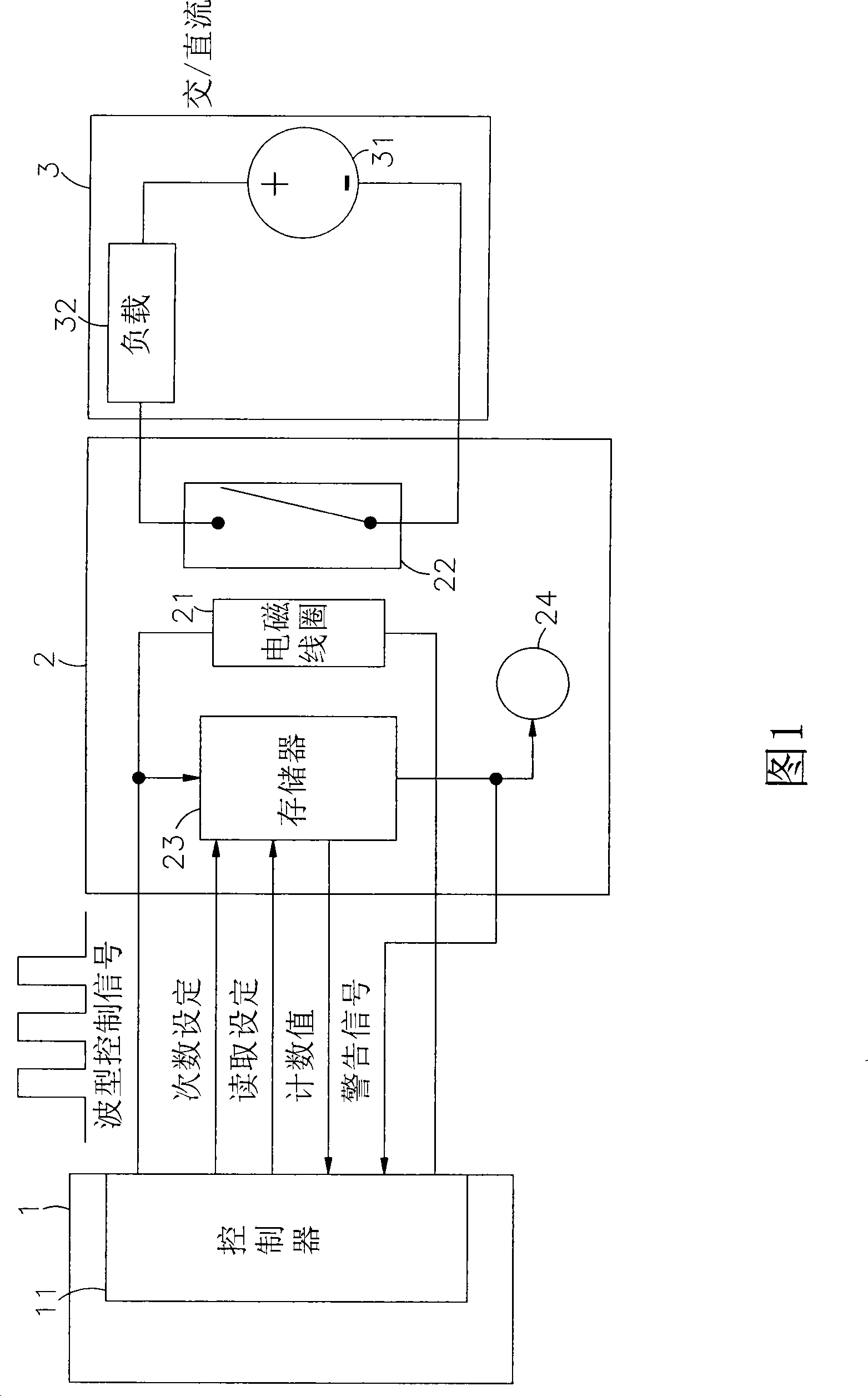
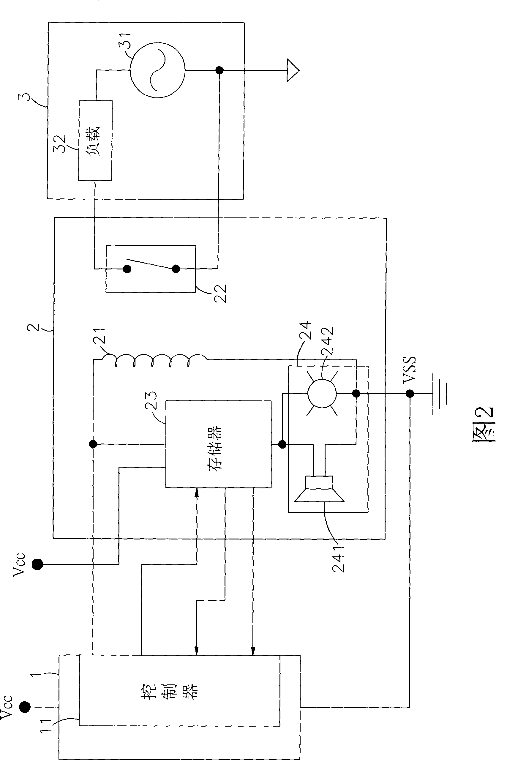
[0019] Please refer to Fig. 1 and Fig. 2, which are circuit block diagrams and circuit diagrams of preferred embodiments of the present invention. It can be clearly seen from the figures that the present invention includes an electronic device 1, a relay module 2 and a power control circuit. Composed of 3, of which:

[0020] The electronic device 1 has a controller 11 inside, and the controller 11 can generate a control signal and transmit the control signal to the inside of the relay module 2 to trigger the action of the primary side electromagnetic coil 21, and the electronic device 1 can It is a computer, man-machine interface or other electronic equipment with output / input control interface.

[0021] The relay module 2 has an electromagnetic coil 21 inside, and whenever the electromagnetic coil 21 on ...


PUM


Abstract

The invention relates to a relay with service-life memory function and a device thereof. A solenoid coil capable of receiving control signals transmitted by an electronic device controller is positioned in a relay module, the control signals are utilized to trigger excitation of a primary side solenoid coil so as to lead a secondary side change-over switch to present on or off states, the change-over switch is connected with a power input device and a load of a power control circuit, further, with the controller, the motion frequency of the change-over switch of the relay module can be stored in a memory, and when the switching frequency reaches the predetermined counting value, warning signals can be automatically sent to warn and inform users to substitute the relay module which is about to fault or at the end of service life due to contact aging in advance, thereby avoiding shortages of damages, stoppage or burning-out of the controlled load due to short circuit or faults of the relay module.

Description

technical field [0001] The present invention relates to a relay with a life memory function and its device, especially a controller that can store the switching times of the relay module in the memory, and when the switching times reach the predetermined count value, it can automatically Send a warning signal to inform the user to replace the relay module that is about to fail due to contact aging or has expired. Background technique [0002] Relays are widely used nowadays. Most of the relays operate on the principle that the primary side electromagnetic coil is excited to cause the secondary side contacts to be closed or opened, so that the relay can be used as As an electronic control device, in actual use, it is used as an automatic switch that controls a large current with a small current, and plays the role of automatic adjustment, safety protection and conversion circuit in the automatic control circuit, while This kind of relay has a wide range of applications, and ...

Claims


Application Information

Patent Timeline
Patent Type & Authority Applications(China)
IPC IPC(8): H01H50/00G01R31/327G06F12/00G08B3/10G08B5/22G06F3/00H02J7/00
Inventor 何盛仁吴坤男
Owner MOXA INC
Why Eureka
Try Eureka