Initial position detection method for permanent magnet synchronous electric motor rotor

A permanent magnet synchronous motor and rotor initial position technology, applied in the control of generators, motor generators, electromechanical transmissions, etc., can solve the problems of complex installation, large impact on rotor structure, and high cost

Inactive Publication Date: 2009-06-17
东元总合科技(杭州)有限公司
View PDF0 Cites 28 Cited by
  • Summary
  • Abstract
  • Description
  • Claims
  • Application Information

AI Technical Summary

Problems solved by technology

The sensor method is simple to use, but the installation is complicated and the cost is high; the high-order harmonic injection method and the observer-based position detection method in the sensorless method are more complex and difficult to implement, and the salient polarity based on inductance saturation is affected by the rotor structure Big

Method used


Image

  • Initial position detection method for permanent magnet synchronous electric motor rotor
  • Initial position detection method for permanent magnet synchronous electric motor rotor
  • Initial position detection method for permanent magnet synchronous electric motor rotor

Examples


Embodiment 1

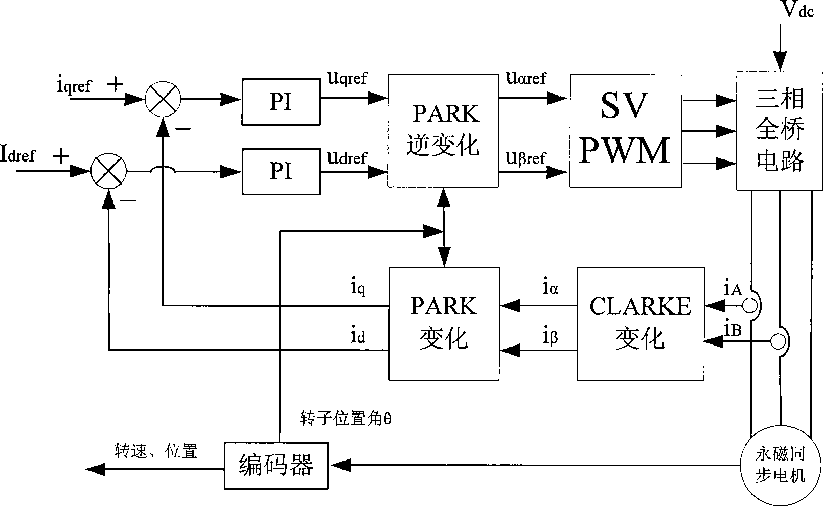
[0026] Such as figure 1 As shown, in the current loop of permanent magnet synchronous motor vector control, two-phase currents in the three-phase currents of the motor are usually sampled (the sum of the three-phase currents is zero, so the other phase can be calculated), and then through the CLARKE change and The feedback current value id, iq is obtained by the change of PARK, the difference between the reference current idref, iqref and the feedback value id, iq is adjusted by PI to obtain udref, uqref, and then uαref, uβref are obtained by inverse change of PARK, and finally the voltage is changed by SVPWM Pulses are applied to a permanent magnet synchronous motor.

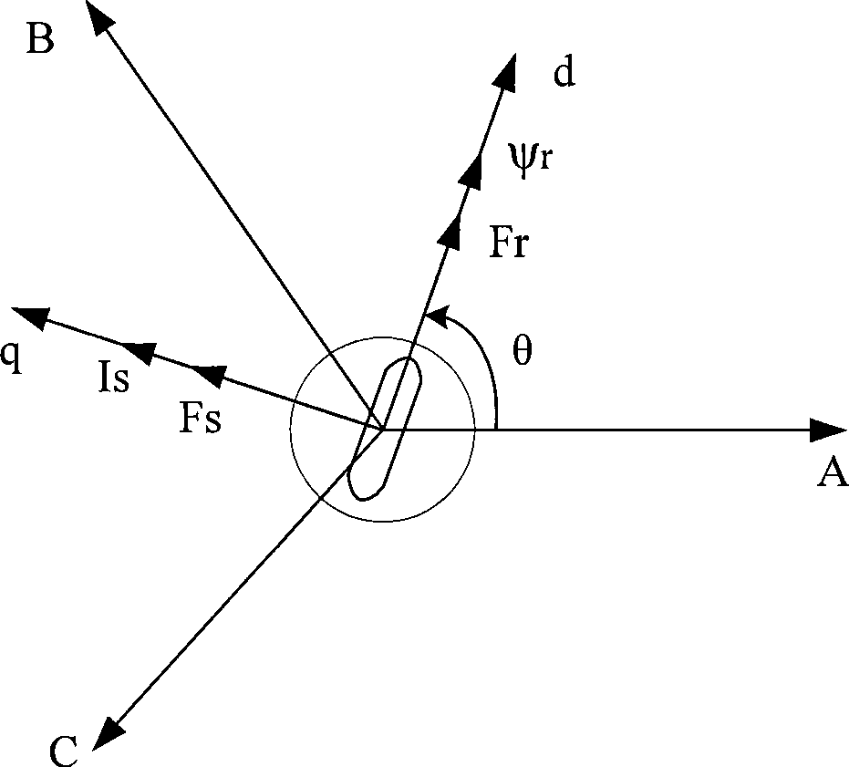
[0027] see figure 2 , the stator current vector Is is adjusted by the two quantities of id and iq, and the coordinate changes required to obtain the feedback values ​​of id and iq are based on the rotor position angle θ, so if the rotor position angle θ is inaccurate, it is bound to It will cause the stator ...

Embodiment 2

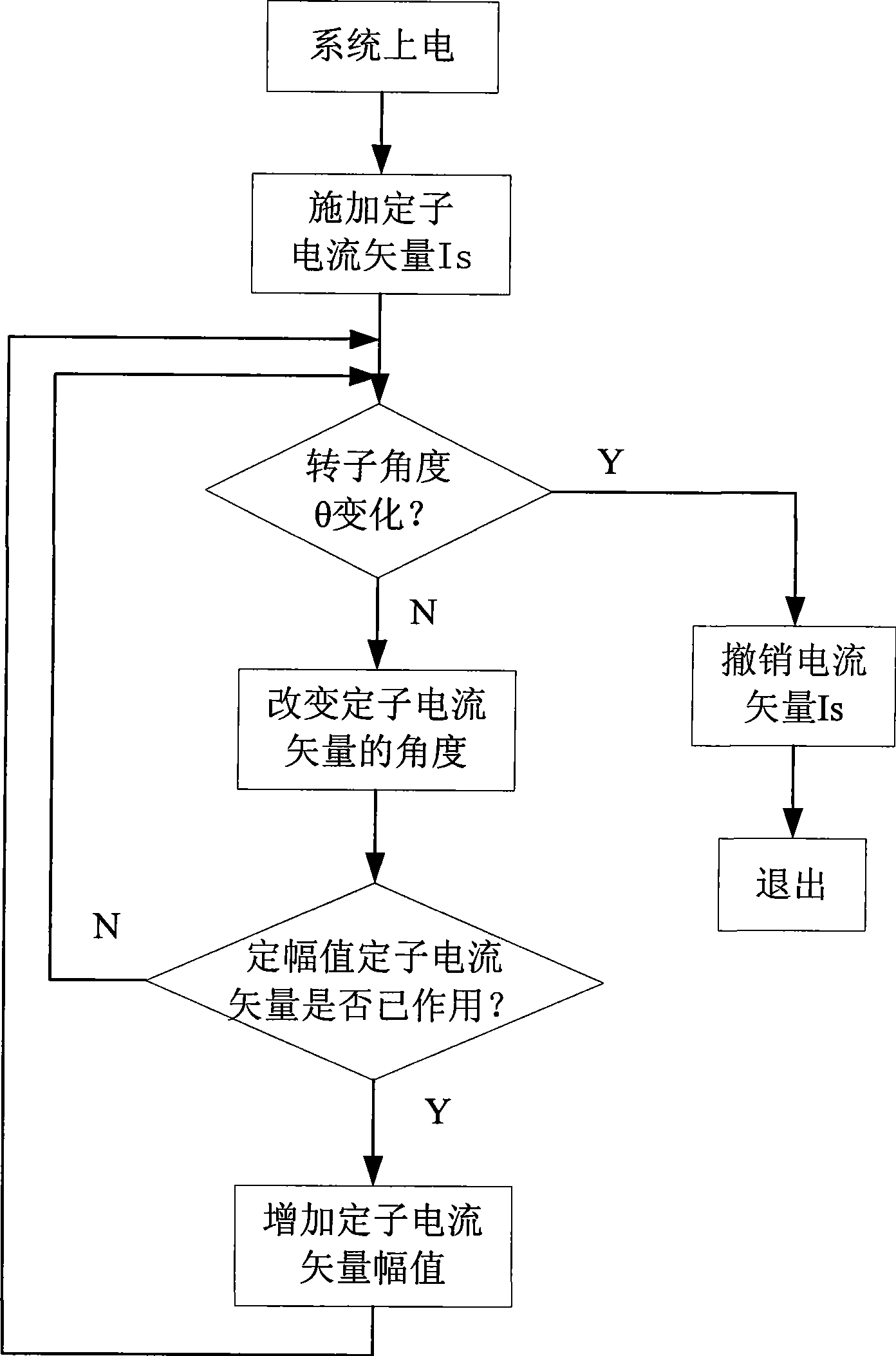
[0035] see Figure 5 , in this embodiment, the system is powered on first, and then the initial stator voltage vector Us1 is applied to the stator of the permanent magnet synchronous motor. Because the initial voltage vector Us1 is too large, the direction of the stator voltage vector Us and the rotor position angle are not 90 degrees, causing the rotor to rotate, which makes the detection of the initial rotor position angle θ inaccurate.

[0036] Then use the incremental photoelectric encoder feedback pulse to detect whether there is a slight displacement of the rotor. The accuracy of the incremental photoelectric encoder is ±360 / (P×4) mechanical angle, and P is the bus number of the incremental photoelectric encoder. The bus number of quantitative photoelectric encoders can reach 2000, which ensures the accuracy of rotor initial position detection.

[0037] If the rotor has a micro position, cancel the effect of the initial voltage vector Us1 immediately, and obtain the ini...


PUM


Abstract

The invention provides a non sensor method for detecting the rotor initial position of a permanent magnet synchronous motor with a simply-assembled incremental encoder, which comprises changing relative magnetic potentials through controlling a driver to output currents and voltage vectors with different directions and amplitudes, namely the interaction with the rotor magnetic potential, then judging the position of the rotor magnetic potential through analyzing the micro-motion of the rotor, finally obtaining the rotor initial position. The invention is unnecessary to compare larger stator current values for increasing the angle resolution like a high frequency injection method, and has the advantages of small noise and extremely weak vibration, simultaneously, can not affect the identification precision.

Description

technical field [0001] The invention relates to a method for detecting the initial position of the rotor of a permanent magnet synchronous motor, more specifically, a method for judging the initial position of the rotor of the motor by using micro-displacement. Background technique [0002] The permanent magnet servo drive system usually adopts vector control, which uses the change from the stationary coordinate system to the rotating coordinate system to realize the decoupling of the excitation component and torque component in the stator current, so that the permanent magnet synchronous motor can be like a DC The magnetic flux and torque are independently controlled as in the motor. The detection of the rotor position of the permanent magnet synchronous motor is a necessary condition for the decoupling of the vector control. Only when the rotor position is accurately known, can the permanent magnet synchronous motor be equivalent to the equivalent model on the dq coordinat...

Claims


Application Information

Patent Timeline
Patent Type & Authority Applications(China)
IPC IPC(8): H02P21/00H02P21/14H02P21/32
Inventor 邹积浩周晖
Owner 东元总合科技(杭州)有限公司
Why Eureka
Try Eureka