Full digital monitoring system with low latency

A monitoring system, all-digital technology, applied in the direction of closed-circuit television systems, televisions, electrical components, etc., can solve the problems of small reliable transmission distance, high complexity, and difficult expansion of analog signals, and achieve low delay, low real-time control, and easy The effect of maintenance

Inactive Publication Date: 2009-06-17
杭州恒生数字设备科技有限公司
View PDF0 Cites 14 Cited by
  • Summary
  • Abstract
  • Description
  • Claims
  • Application Information

AI Technical Summary

Problems solved by technology

The advantage of the system designed in this way is that what you see at the console is an analog signal, and the delay is small. The disadvantage is that the re

Method used


Image

  • Full digital monitoring system with low latency
  • Full digital monitoring system with low latency
  • Full digital monitoring system with low latency

Examples


Example Embodiment

[0040] Example 1:

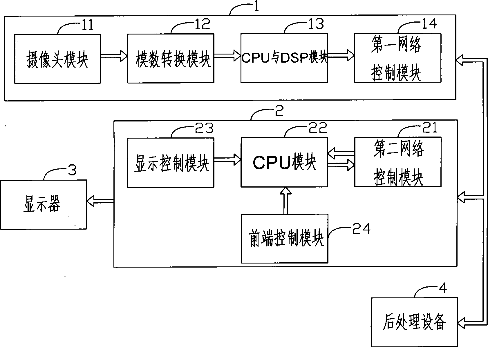
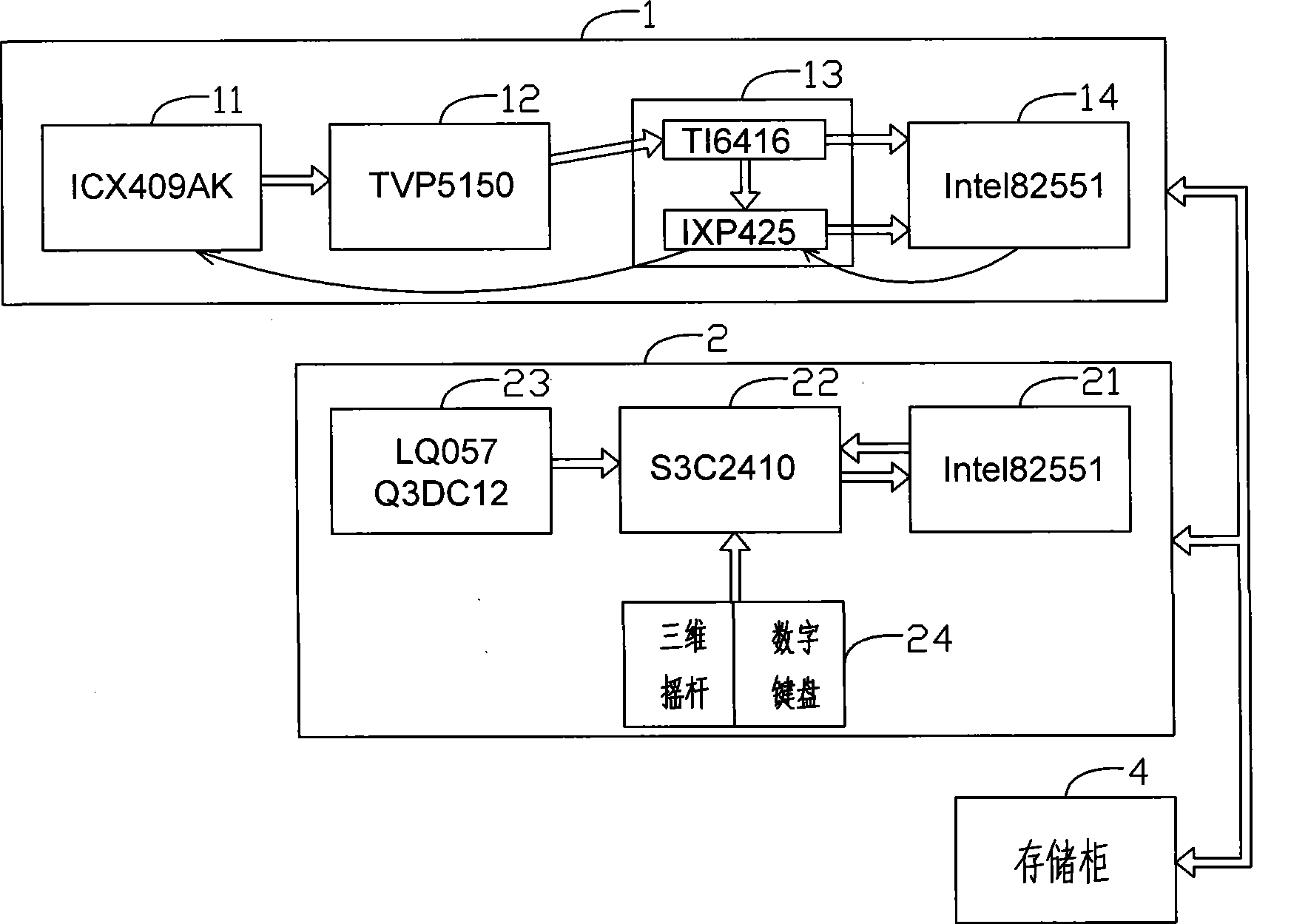
[0041] This embodiment is an actual digital surveillance system used in a grassroots police station. The video signal encoder 1 is installed on a square in a commercial area, and the computer 2 is an embedded device with a display module, which is installed at the console of the police station. A storage cabinet as a post-processing device 4 is also installed at the console to store, retrieve, and replay the compressed video signal transmitted from the monitoring front end.

[0042] The camera module 11 of the video signal encoder 1 uses Samsung's CCD module ICX409AK, the analog-to-digital conversion module 12 uses the TVP5150 chip, the CPU and DSP modules 13 use the DSP chip TI6416 and the CPU chip IXP425, respectively, and the first network control module 14 uses the Intel 82551 chip. The camera module 11 sends the analog video signal collected on site to the analog-to-digital conversion module 12. The analog-to-digital conversion module 12 samples and quanti...

Example Embodiment

[0044] Example 2:

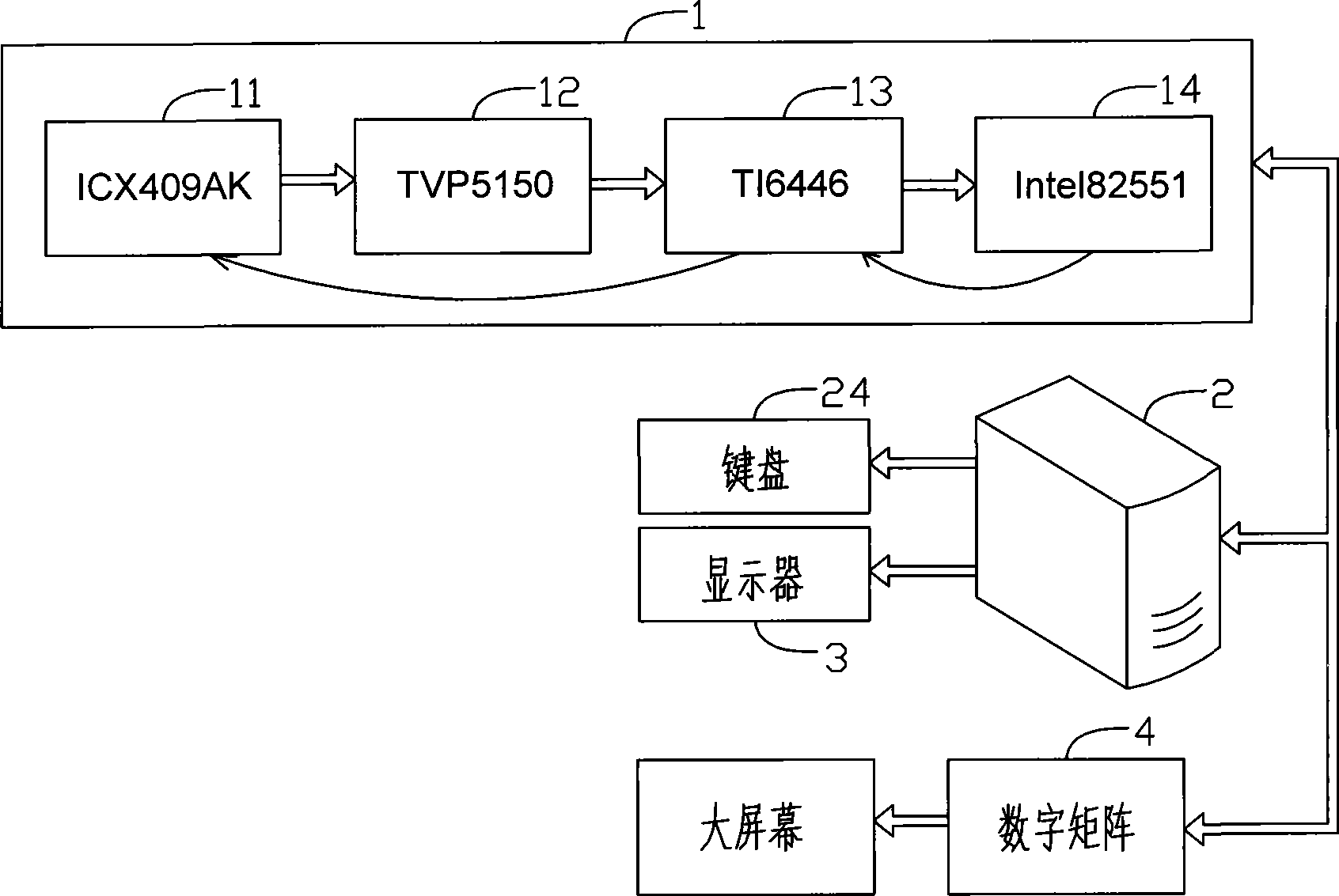
[0045] This embodiment is a digital monitoring system for railway stations. The video signal encoder 1 is installed in the waiting room, the computer 2 is a PC, the external keyboard of the PC is used as the front-end control module 24, the PC is connected to the external monitor 3, and the computer 2 and the monitor 3 are installed in the control room of the railway station. Station. The console is also installed with a digital matrix as a post-processing device 4 for storing, retrieving, and replaying the compressed video signal transmitted from the monitoring front end. For the convenience of viewing, a large screen is also connected to the digital matrix.

[0046] The camera module 11 of the video signal encoder 1 uses Samsung’s CCD module ICX409AK, the analog-to-digital conversion module 12 uses the TVP5150 chip, and the CPU and DSP module 13 uses the TI6446 chip. The TI6446 chip is a chip that integrates the DSP and the CPU. The network control module 14 ...


PUM


Abstract

The invention discloses a low-delay all-digital monitoring system, which comprises a video signal coder, a computer and a display which are orderly connected, wherein the video signal coder comprises a camera module, an analog-digital conversion module, a CPU and DSP module and a first network control module, wherein the computer comprises a second network control module, a CPU module, a display control module and a front end control module. Except for compressing and coding or packing and transmitting YUV format signals, the CPU and DSP module further abstracts the YUV format signals into video signals, then packing an transmitting, the computer displays the video signals on the display after receiving the video signals, thereby the condition of the monitoring front end can be observed in real time, when the camera module needs to be adjusted, the control orders are analyzed by the CPU and DSP module, and results are transmitted to the camera module, and simultaneously, the camera module embodies the executing results of the control orders on the display. Video signals whose low-delay is the same with a simulated system can be seen from the control station, the complexity is reduced, the cost is low and the maintenance is easy.

Description

technical field [0001] The invention relates to a digital monitoring system, in particular to a low-delay all-digital monitoring system. Background technique [0002] At present, the monitoring system has shifted from analog monitoring to digital monitoring. Compared with analog monitoring, the advantages of digital monitoring are compressibility, easy storage and transmission, and easy intelligent processing, such as retrieval and identification. However, digital monitoring also has shortcomings. There are two main shortcomings: one is that the compression of digital images is lossy compression, and the clarity of the compressed image decreases; the other is that the delay caused by compression and decompression is relatively large. The delay time is determined by the complexity of the compression algorithm and the processing capability of the system. The delay of mainstream systems is generally around 500ms. [0003] Regarding the first shortcoming of the digital monitor...

Claims


Application Information

Patent Timeline
IPC IPC(8): H04N7/18H04N7/26
Inventor 查敏中
Owner 杭州恒生数字设备科技有限公司
Why Eureka
Try Eureka