High speed electric principal shaft supported by AC mixing magnetic bearing

A technology of hybrid magnetic bearing and high-speed motorized spindle

Inactive Publication Date: 2009-06-24
JIANGSU UNIV
View PDF0 Cites 23 Cited by
  • Summary
  • Abstract
  • Description
  • Claims
  • Application Information

AI Technical Summary

Problems solved by technology

[0005] The rotor of the traditional magnetic levitation electric spindle system is supported by 3 DC hybrid magnetic bearings, including 2 radial magnetic bearings, each radial magnetic bearing controls two radial directions perpendicular to each other, and the other 1 axial thrust magnetic bearing Control the axial degree of freedom; using DC control, the DC power amp

Method used


Image

  • High speed electric principal shaft supported by AC mixing magnetic bearing
  • High speed electric principal shaft supported by AC mixing magnetic bearing
  • High speed electric principal shaft supported by AC mixing magnetic bearing

Examples


Embodiment 1

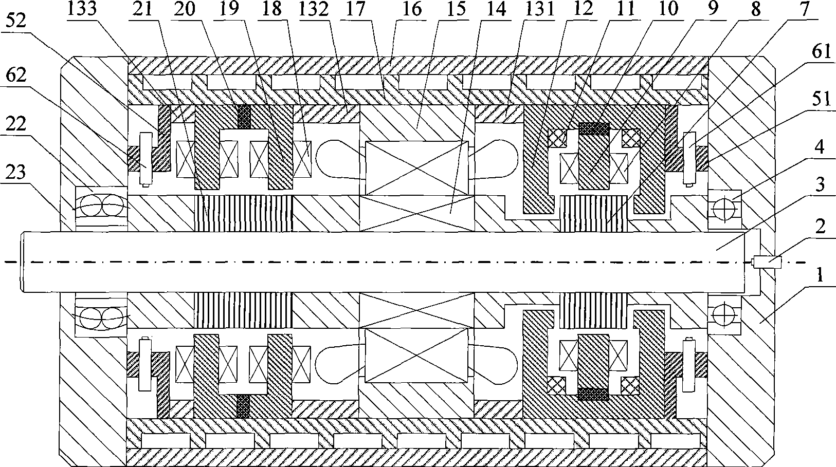
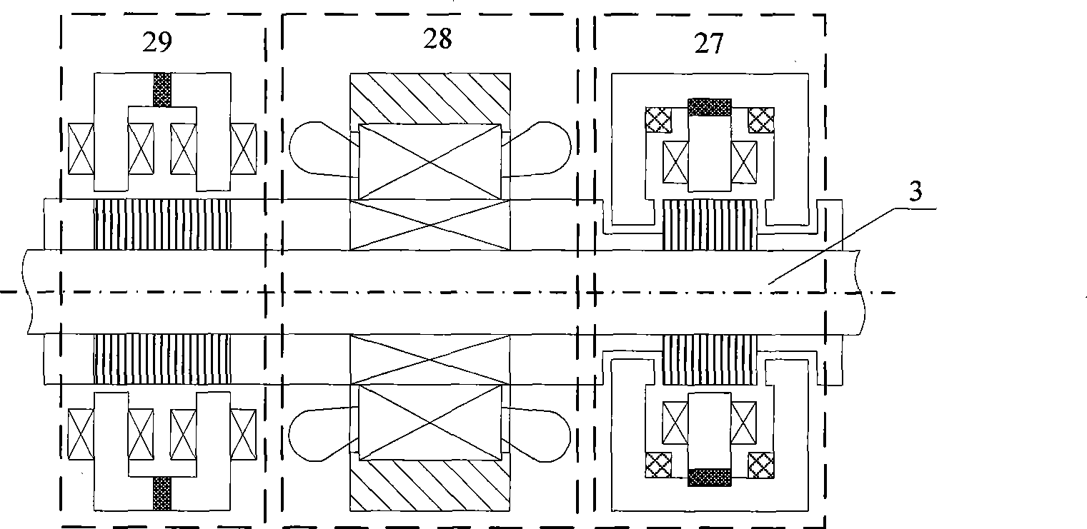
[0039] Such as figure 1 with figure 2 As shown, the high-speed electric spindle system supported by the five-degree-of-freedom AC hybrid magnetic bearing, its mechanical structure is mainly composed of the AC-DC three-degree-of-freedom hybrid magnetic bearing 27, the high-speed spindle motor 28, the AC two-freedom It consists of a hybrid magnetic bearing 29, a rotating shaft 3, a right end cover 1 and a left end cover 23. figure 1 Among them, the axial displacement sensor probe 2 is installed on the right end cover 1, on the axis line of the rotating shaft 3, and detects the axial displacement of the rotating shaft 3; the radial auxiliary bearing 4 is fixed in the right end cover 1; 4 radial displacements at the right end The sensor probes 61 are evenly distributed along the circumference and fixed on the right end sensor bracket 51 between the right end cover 1 and the AC / DC three-degree-of-freedom hybrid magnetic bearing 27 to detect the radial displacement of the right en...

Embodiment 2

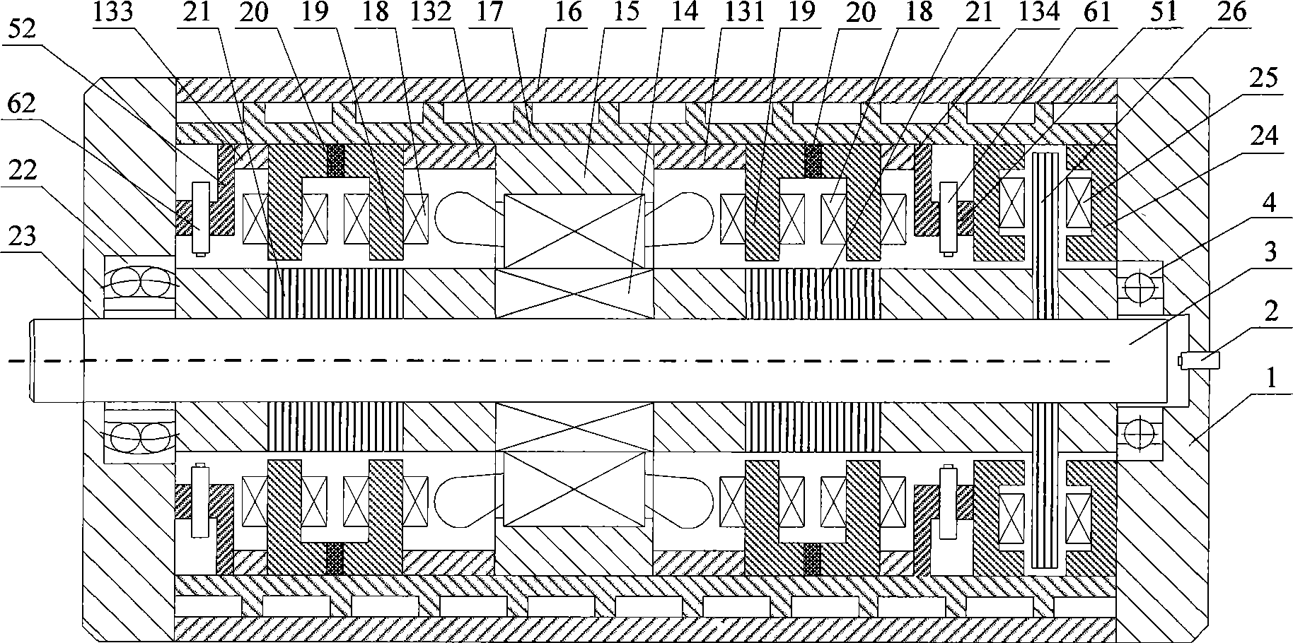
[0047] Such as image 3 with Figure 4 As shown, the high-speed motorized spindle system supported by a five-degree-of-freedom AC hybrid magnetic bearing has a mechanical structure mainly composed of a high-speed spindle motor 28 pressed into a steel cylinder inner sleeve 17, two AC two-degree-of-freedom hybrid magnetic bearings 29, and a shaft It consists of a DC active magnetic bearing 30, a rotating shaft 3, a right end cover 1 and a left end cover 23; image 3 Among them, the radial auxiliary bearing 4 and the radial-axial auxiliary bearing 22 are respectively installed in the right end cover 1 and the left end cover 23; the axial displacement sensor probe 2 is installed on the right end cover 1, on the axis line of the rotating shaft 3, Detect the axial displacement of the rotating shaft 3; the axial DC active magnetic bearing 30 is installed close to the right end cover 1, the left side of which is the right end sensor bracket 51, and the four radial displacement sensor...


PUM


Abstract

The invention relates to a high-speed electric spindle supported by an alternating current hybrid magnetic bearing, comprising an AC/DC three freedom-degree hybrid magnetic bearing which is pressed in a steel cylinder, a high-speed spindle motor, an AC two freedom-degree hybrid magnetic bearing, a left end cover, a right end cover and a rotating shaft; the high-speed spindle motor is arranged on the rotating shaft; the AC/DC three freedom-degree hybrid magnetic bearing and the AC two freedom-degree hybrid magnetic bearing are respectively arranged on the left and right sides of the high-speed spindle motor. Static bias magnetic flux is provided for each freedom degree by adopting permanent magnet, and the radial directions of the AC/DC three freedom-degree hybrid magnetic bearing and the AC two freedom-degree hybrid magnetic bearing adopt a three pole structure and a three-phase inverter for drive control, thus remarkably reducing the loss and cost of a power amplifier. The high-speed electric spindle realizes zero intermediate transmission and has the advantages of no mechanical friction, no lubrication and sealing, high speed, high precision and low power consumption; therefore, the high-speed electric spindle has application prospect in the field of mechanical industry, space flight and aviation and the like.

Description

technical field [0001] The invention belongs to the technical field of electromechanical transmission equipment control, and belongs to the field of non-contact magnetic levitation rotating machinery, especially refers to a high-speed electric spindle system supported by a five-degree-of-freedom AC hybrid magnetic bearing, and is suitable for five-degree-of-freedom of various high-speed and high-precision rotating machinery Suspension support can be used in special occasions such as vacuum technology, clean room, aseptic workshop, and transmission of corrosive media or very pure media. Alternate application value. Background technique [0002] Magnetic bearing is a high-tech electromechanical integration product that uses magnetic field force to suspend the rotor in space and realizes no mechanical contact between the rotor and the stator. The motor transmission system supported by magnetic bearings has the advantages of high speed, low power consumption, no friction, no we...

Claims


Application Information

Patent Timeline
IPC IPC(8): H02K7/09F16C32/04H02N15/00
Inventor 朱熀秋邬清海
Owner JIANGSU UNIV
Why Eureka
Try Eureka