Low profile side emitting led

A technology of light-emitting diodes and light-emitting devices, applied in semiconductor devices, electrical components, circuits, etc.

Active Publication Date: 2009-06-24
PHILIPS LUMILEDS LIGHTING CO LLC
View PDF2 Cites 33 Cited by
  • Summary
  • Abstract
  • Description
  • Claims
  • Application Information

AI Technical Summary

Problems solved by technology

Side emission without lens

Method used


Image

  • Low profile side emitting led
  • Low profile side emitting led
  • Low profile side emitting led

Examples


Embodiment Construction

[0024] Embodiments of the present invention include thin profile side-emitting LEDs that enable thin backlight structures for liquid crystal display applications and other applications.

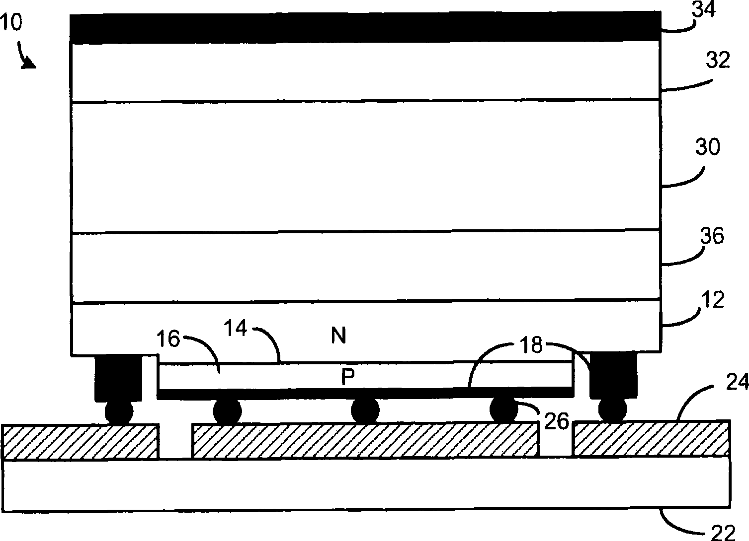
[0025] figure 1 is a side view of a first embodiment of a side-emitting light-emitting diode 10 . In one embodiment, the thickness of the side emitting surface is 0.2-0.4 mm. In another embodiment, the thickness of the side light-emitting surface is 0.2-0.6 mm.

[0026] The invention can be applied to LEDs made of any material system, such as AlInGaP (typically used to emit red to yellow light) or GaN (typically used to emit green to ultraviolet light). Light emitting diodes are formed on a starting growth substrate such as sapphire, SiC, or GaAs, depending on the type of light emitting diode to be formed. Generally, the n-type layer 12 is formed first, then the active layer 14 is formed, and then the p-type layer 16 is formed. The p-type layer 16 is etched to expose a portion of the unde...


PUM


Abstract

Low profile, side-emitting LEDs (10) are described, where all light is efficiently emitted within a relatively narrow angle generally parallel to the surface of the light- generating active layer (14). The LEDs enable the creation of very thin backlights for backlighting an LCD. In one embodiment, the LED is a flip chip with the n and p electrodes (18) on the same side of the LED, and the LED is mounted electrode-side down on a submount (22). A reflector (34) is provided on the top surface of the LED so that light impinging on the reflector is reflected back toward the active layer (14) and eventually exits through a side surface of the LED. A waveguide layer (30) and / or one or more phosphors layers are deposed between the semiconductor layers (12, 14, 16) and the reflector for increasing the side emission area for increased efficiency. Side-emitting LEDs with a thickness of between 0.2-0.4 mm can be created.

Description

technical field [0001] This invention relates to lighting devices using non-laser light-emitting diodes (LEDs), and more particularly to improvements to backlights and other similar lighting devices using side-emitting LEDs. Background technique [0002] Liquid crystal displays (LCDs) are often used in mobile phones, personal digital assistants (PDAs), laptop computers, desktop monitors, and television applications. One embodiment of the invention relates to a color transmissive liquid crystal display requiring a backlight, where the backlight may use one or more light emitting diodes, emitting white or colored light. LEDs differ from laser diodes in that LEDs emit incoherent light. [0003] In many small displays, such as for mobile phones, personal digital assistants, and other devices, it is important that the display be thin. Furthermore, since such small displays are usually battery operated, it is important that the light from the LEDs be efficiently coupled to the b...

Claims


Application Information

Patent Timeline
Patent Type & Authority Applications(China)
IPC IPC(8): H01L33/00H01L33/22H01L33/38H01L33/46H01L33/50H01L33/60
CPCH01L33/46H01L33/22H01L33/38H01L33/50H01L33/60H01L2224/13
Inventor O·B·什赫金M·皮尤G·哈伯斯M·R·克雷姆斯J·E·埃普勒
Owner PHILIPS LUMILEDS LIGHTING CO LLC
Why Eureka
Try Eureka