Check patentability & draft patents in minutes with Patsnap Eureka AI!

Exposure apparatus and device manufacturing method

A technology for exposure devices and optical components, which is used in the manufacture of semiconductor/solid-state devices, exposure devices for photoengraving processes, optical components, etc., can solve the problem of rusting of the lens barrel of optical components, deterioration of exposure accuracy, measurement accuracy, and dissolution of optical components. and other problems to achieve the effect of preventing immersion

Inactive Publication Date: 2009-07-01
NIKON CORP
View PDF19 Cites 0 Cited by
  • Summary
  • Abstract
  • Description
  • Claims
  • Application Information

AI Technical Summary

Problems solved by technology

[0010] Furthermore, in the above-mentioned prior art, in order to form a liquid immersion region, a nozzle member having a liquid supply port and a liquid recovery port is used to supply and recover liquid, but when the liquid enters the gap between the nozzle member and the projection optical system, When used, there is a possibility of rust on the lens barrel holding the optical components constituting the projection optical system, or problems such as melting of the optical components may occur.
[0011] Furthermore, it is also considered that the liquid infiltrates the inside of the lens barrel, and in this case, the above-mentioned disadvantages may also occur.
[0012] In addition, due to the influence of the immersed liquid, for example, the optical components on the side closest to the image plane in the projection optical system are slightly deformed or vibrated, and exposure accuracy and measurement accuracy may deteriorate.

Method used


Image

  • Exposure apparatus and device manufacturing method
  • Exposure apparatus and device manufacturing method
  • Exposure apparatus and device manufacturing method

Examples


no. 1 Embodiment

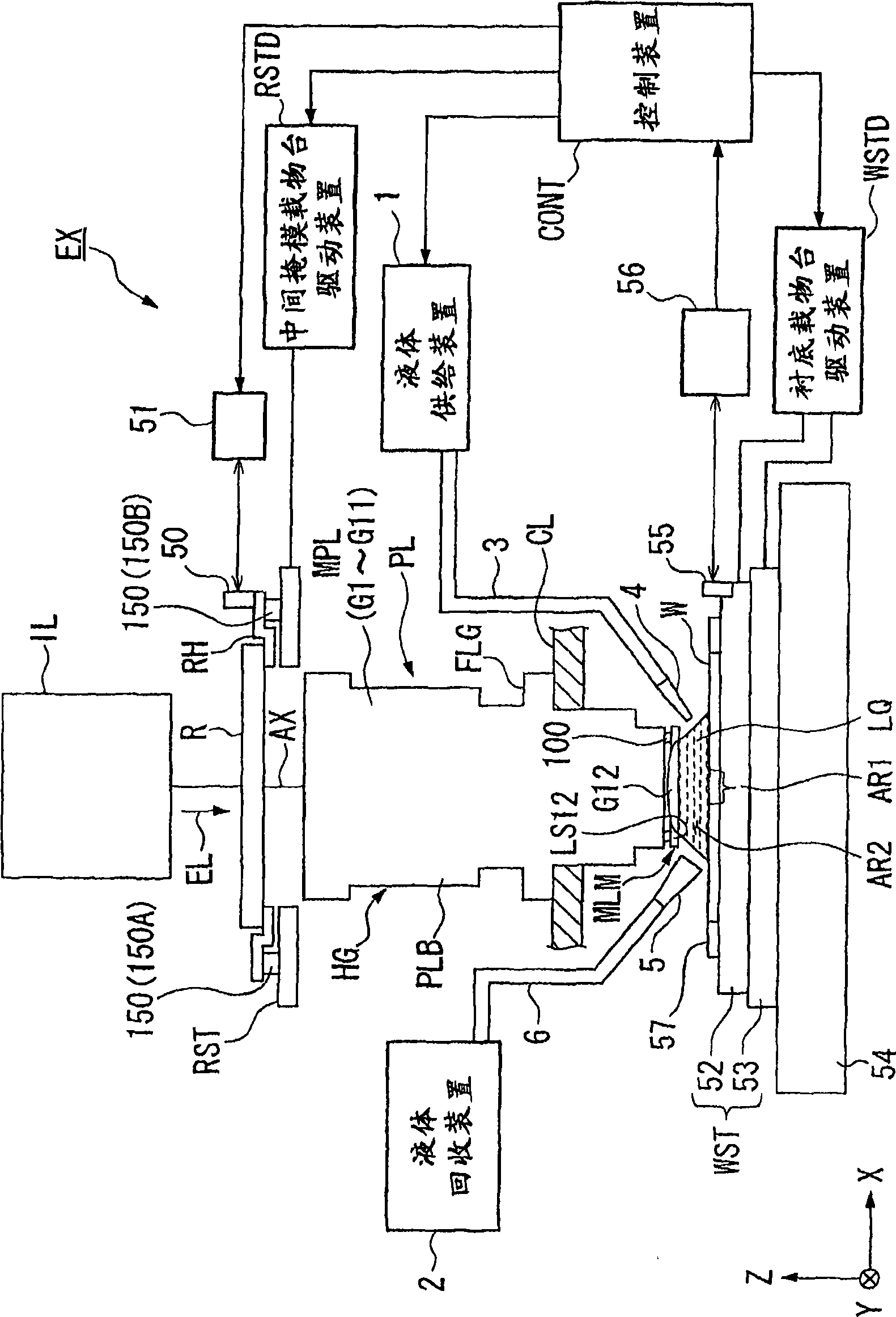
[0042] figure 1 It is a schematic configuration diagram showing one embodiment of the exposure apparatus of the present invention.

[0043] exist figure 1 Among them, the exposure apparatus EX is equipped with a reticle stage RST supporting the reticle R, a substrate stage WST supporting the substrate W, and illuminating the middle stage supported on the reticle stage RST with the exposure light EL. The illumination optical system IL of the mask R, the projection optical system PL for projecting and exposing the image of the pattern of the reticle R illuminated with the exposure light EL onto the substrate W supported on the substrate stage WST, and the unified control A control device CONT for the overall operation of the exposure apparatus EX.

[0044] Here, in this embodiment, as the exposure apparatus EX, the reticle R and the substrate W are moved synchronously in directions different from each other in the scanning directions (opposite directions), and the substrate ...

no. 2 Embodiment

[0096] Further, the exposure apparatus of the present invention will be described with reference to the drawings. Figure 10 It is a schematic configuration diagram showing one embodiment of the exposure apparatus of the present invention.

[0097] exist Figure 10 Among them, the exposure apparatus EX is provided with a mask stage MST supporting the mask M, a substrate stage PST supporting the substrate W, and illuminating the mask M supported on the mask stage MST with the exposure light EL. The illumination optical system IL, the projection optical system PL for projecting and exposing the pattern image of the mask M illuminated with the exposure light EL onto the substrate W supported on the substrate stage PST, and collectively controlling the operation of the entire exposure apparatus EX The control device CONT.

[0098] The exposure apparatus EX of this embodiment is a liquid immersion exposure apparatus to which a liquid immersion method is applied in order to substa...


PUM

PropertyMeasurementUnit
refractive indexaaaaaaaaaa

Abstract

An exposure apparatus EX projects a pattern image onto a substrate W via a projection optical system PL and a liquid LQ, and the projection optical system PL has an optical member G12 that comes into contact with the liquid LQ and an optical group MPL arranged between the optical member G12 and a reticle R. A holding mechanism HG that holds the optical member G12 and the optical group MPL holds the optical member G12 so that it is movable relative to the optical group MPL. Through such a configuration, it is possible to provide an exposure apparatus that is able to restrict deterioration of the pattern image when the space between the projection optical system and the substrate is filled with liquid and exposure processing is performed.

Description

[0001] This application is a divisional application of the invention patent application with the application number 200480023855.0, the application date is July 7, 2004, and the invention title is "Exposure Device and Device Manufacturing Method". [0002] This application is based on Japanese Patent Application No. 2003-272614 (filed on July 9, 2003) and Japanese Patent Application No. 2004-044801 (filed on February 20, 2004), which are patent applications filed with the Japan Patent Office, and refers to its content. technical field [0003] The present invention relates to an exposure apparatus for exposing a substrate in a state where the space between a projection optical system and the substrate is filled with liquid, and a device manufacturing method using the exposure apparatus. Background technique [0004] Semiconductor devices and liquid crystal display devices use so-called photolithography to transfer patterns formed on a mask or reticle (hereinafter referred to...

Claims


Application Information

Patent Timeline
Patent Type & Authority Applications(China)
IPC IPC(8): G03F7/20G02B7/02H01L21/027
Inventor 木内彻三宅寿弘
Owner NIKON CORP
Features
  • R&D
  • Intellectual Property
  • Life Sciences
  • Materials
  • Tech Scout
  • Unparalleled Data Quality
  • Higher Quality Content
  • 60% Fewer Hallucinations
Learn More