Electric connection structure and method for heat radiating device and switching circuit board

A technology for switching circuit boards and cooling devices, which is applied in the fields of electrical digital data processing, cooling/ventilation/heating transformation, and instruments, etc., which can solve problems such as inconvenience in maintenance operations, enlarged space of the housing 20, and increased processing costs, etc., to achieve Save processing time, reduce cost, and reduce volume

Inactive Publication Date: 2009-07-01
INVENTEC CORP
View PDF0 Cites 13 Cited by
  • Summary
  • Abstract
  • Description
  • Claims
  • Application Information

AI Technical Summary

Problems solved by technology

[0005] However, the electrical connection structure between the cooling device 13 and the backplane 14 needs to be connected to the connector 132 and the backplane 14 through wires 16, which is extremely inconvenient for assembly and disassembly; and when the system is running, one of the fans 131 fails , it is necessary to unplug the electric wire 16, and then connect a new electric wire between the connector of the new fan and the backplane 14, causing inconvenience to the maintenance work
[0006] In addition, in order to connect the wires 16 between the heat sink 13 and the backplane 14, it is necessary to reserve an appropriate gap width S for placing the wires 16. Therefore, the space in the casing 20 becomes larger, and the server 1 The volume becomes larger, which increases the processing cost

Method used


Image

  • Electric connection structure and method for heat radiating device and switching circuit board
  • Electric connection structure and method for heat radiating device and switching circuit board
  • Electric connection structure and method for heat radiating device and switching circuit board

Examples


Embodiment Construction

[0048] Embodiments of the present invention are described below through specific examples, and those skilled in the art can easily understand other advantages and effects of the present invention from the content disclosed in this specification.

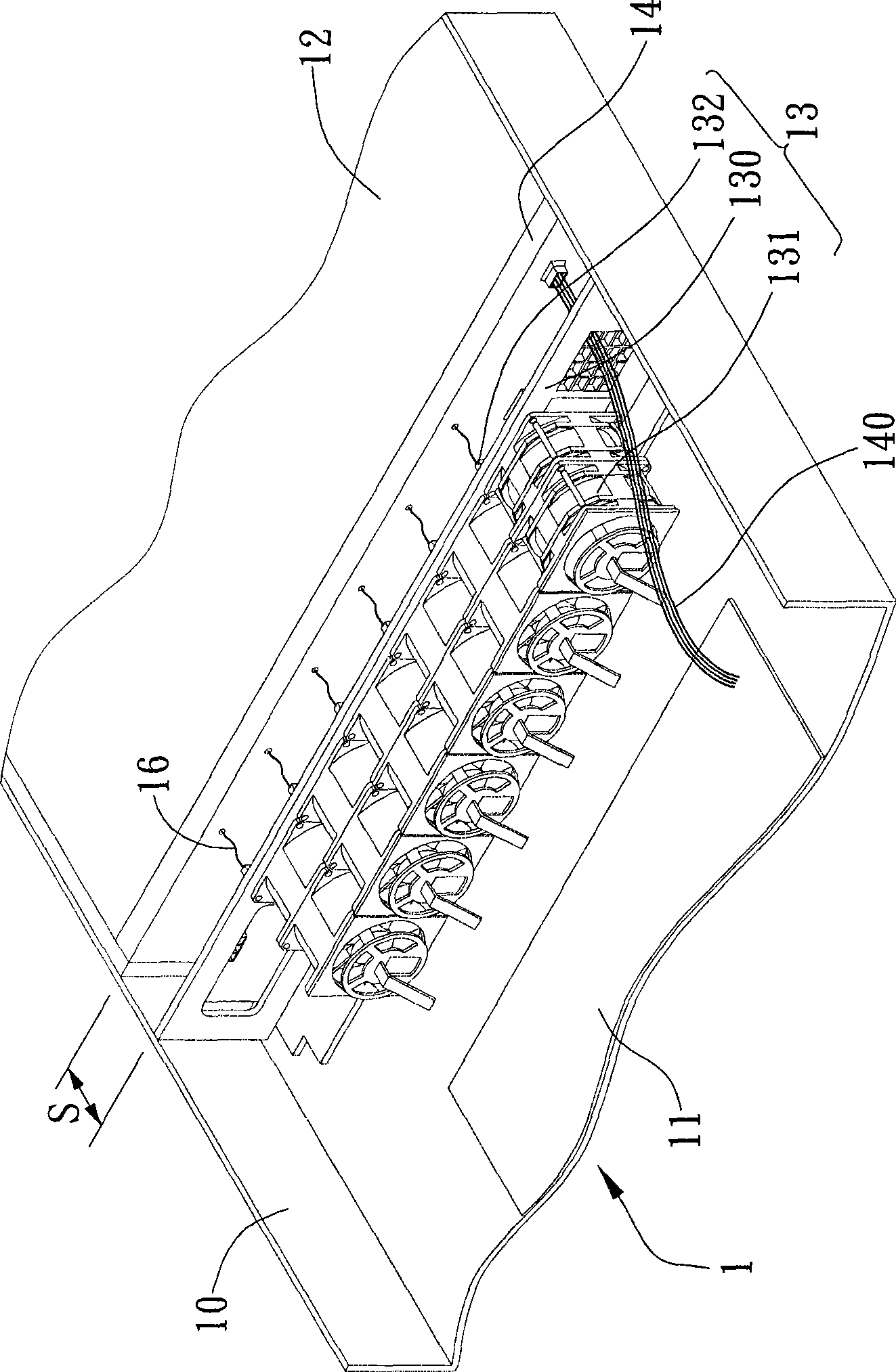
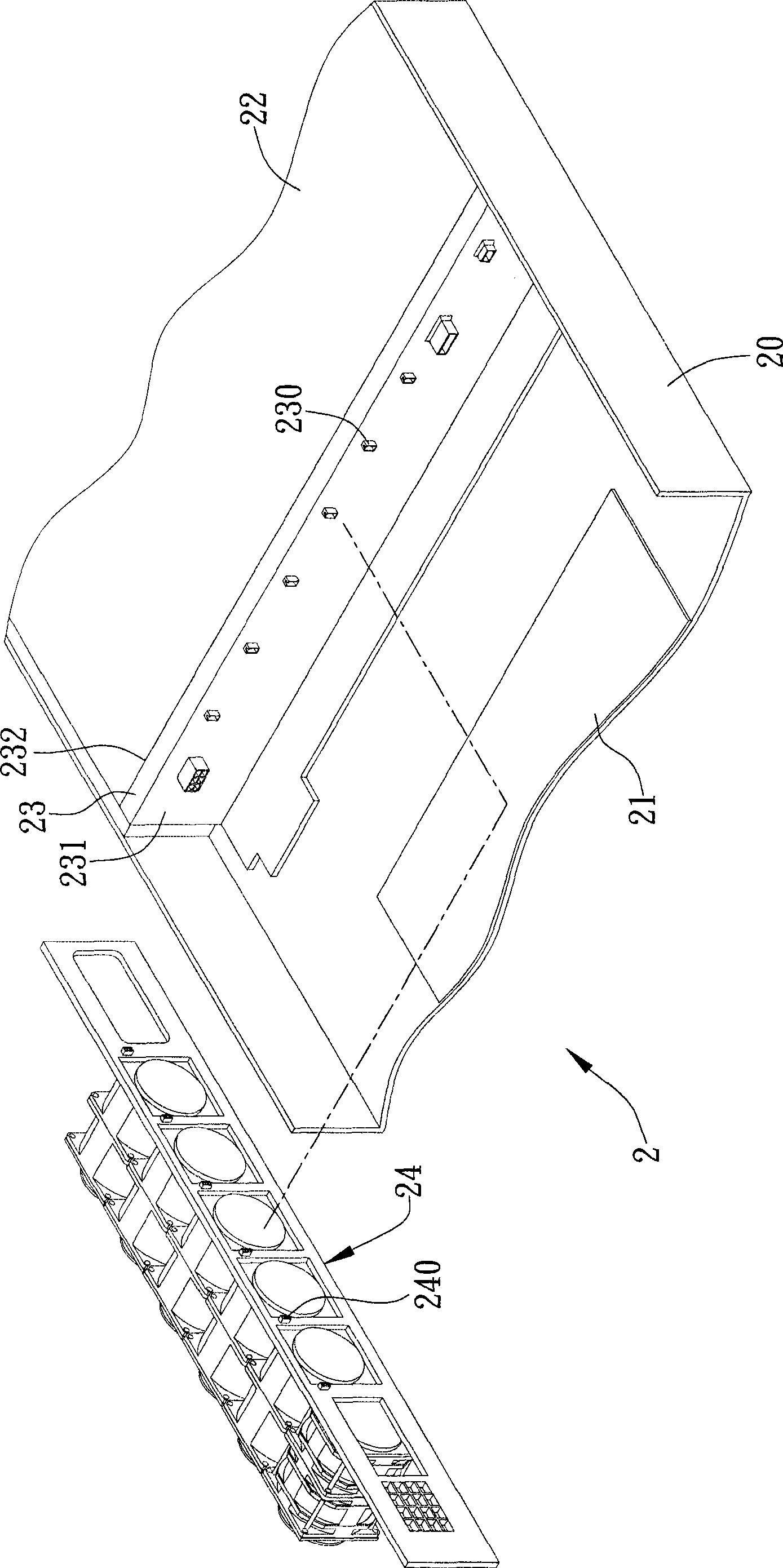
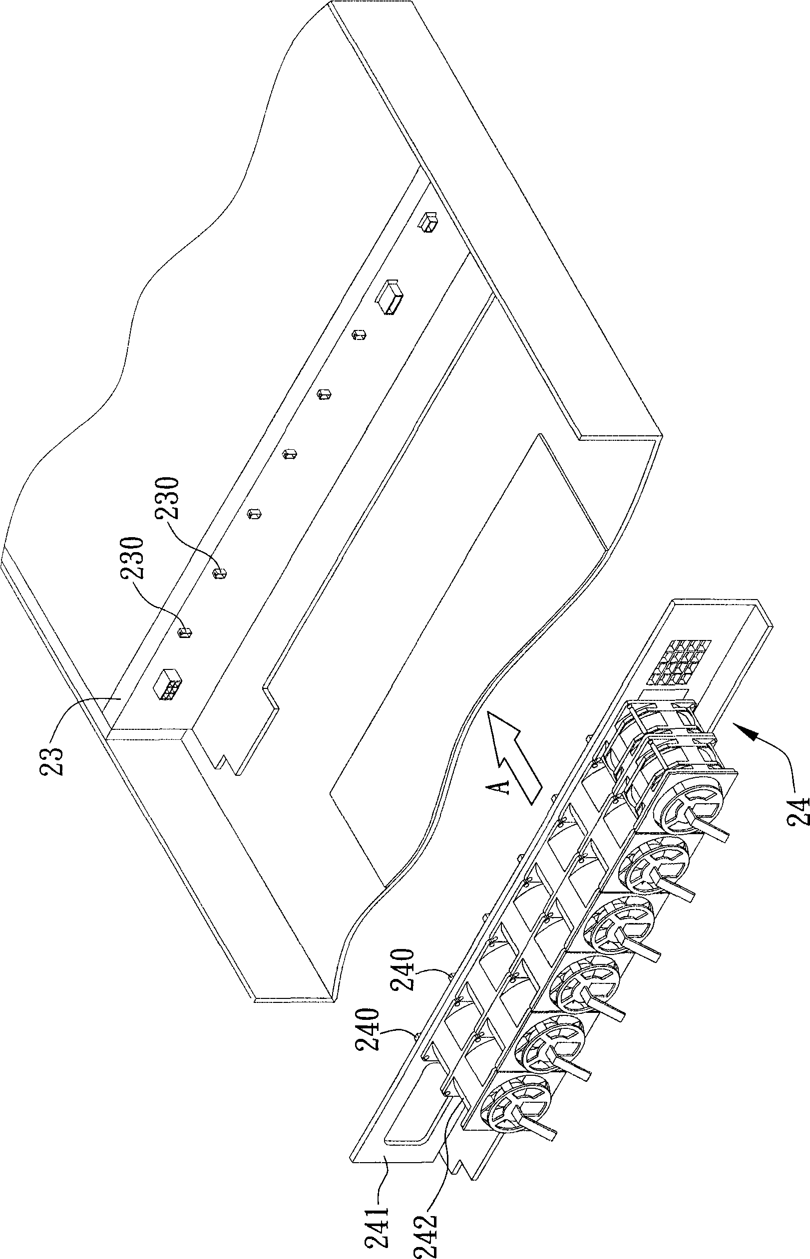
[0049] see figure 2 , is a drawing in which the electrical connection structure of the heat dissipation device and the interposer circuit board of the present invention is applied to an electronic device, such as a server, a notebook computer device, a personal computer, and the like.

[0050] The electronic equipment 2 has a casing 20, a motherboard 21, a hard disk 22, a heat sink 24, and an adapter circuit board 23. The motherboard 21 and the hard disk 22 are all installed in the housing 20, and the adapter circuit board 23 is fixed on The casing 20 has a first surface 231 and a second surface 232 opposite to the first surface 231, the second surface 232 is electrically connected to the hard disk 22, the first surface 231 is elect...


PUM


Abstract

The invention discloses an electrical connection structure for a heat radiating device and a switching circuit board and an electrical connection method, which are used for the inside of an electric device, the electric device is provided with a casing, a mother board, a hard disk and the switching circuit board, wherein the mother board and the hard disk are mounted in the casing, the switching circuit board is fixed on the casing and is electrically connected with the mother board and the hard disk. The electrical connection structure is structurally characterized in that the switching circuit board is equipped with a first connector, and the heat radiating device is equipped with a second connector corresponding to the first connector. The method comprises steps of firstly fixing and electrically connecting the first connector to the switching circuit board, mutually splicing the first and second connectors to electrically connect with the heat radiating device and the switching circuit board, thereby avoiding use of wires electrically connected the heat radiating device to the switching circuit board, thereby further saving assembly time effectively.

Description

technical field [0001] The present invention relates to an electrical connection structure and an electrical connection method thereof, and more specifically, relates to an electrical connection structure and an electrical connection method of a heat sink and an adapter circuit board. Background technique [0002] At present, the electronic equipment is a standard product integrated with multiple hard disks, which has the advantages of common structural size, large number of hard disks, easy hot swapping of hard disks, and failures in RAID (Redundant Array of Inexpensive Disks; RAID). The hard disk performs online replacement and many other advantages. Therefore, the hard disk module is increasingly widely used in the field of computers, especially in the field of servers. [0003] In addition, the hard disk module of the electronic device is used to save important data to ensure the normal operation of the computer system such as the server. At the same time, as the main h...

Claims


Application Information

Patent Timeline
Patent Type & Authority Applications(China)
IPC IPC(8): G06F1/20H05K7/20
Inventor 胡永凉郑再魁
Owner INVENTEC CORP
Why Eureka
Try Eureka