
D/A converter circuit employing multistage amplifier part multiplexing technology

A technology of analog-to-digital converters and multi-stage amplifiers, applied in the direction of analog-to-digital converters, improved amplifiers to improve efficiency, etc., can solve the problem of reducing the settling time performance of the amplification stage, charge injection noise, clock feedthrough, reset or auto-zero failure To achieve the effect of reducing design complexity, reducing gain and bandwidth requirements, and reducing dynamic performance

Active Publication Date: 2009-07-01
SOI MICRO CO LTD
View PDF0 Cites 9 Cited by
  • Summary
  • Abstract
  • Description
  • Claims
  • Application Information

AI Technical Summary

Problems solved by technology

In low-power pipeline analog-to-digital converters, the technology of amplifier multiplexing has been proven to greatly reduce system power consumption, but at the same time, in order to enable amplifiers to be multiplexed by multi-stage pipelines, in order to control complex and circuit structure, too many switches bring a lot of charge injection noise and clock feedthrough effect
[0018] In addition, the traditional appearance clock controls the amplification and reset (or auto-zero) of the amplifier alternately, but in the amplifier multiplexing structure, the amplifier has to undertake the amplification task of the two-stage pipeline structure, so that the reset or auto-zero cannot be performed. , greatly reducing the settling time performance of its amplifying stage

Method used


Image

  • D/A converter circuit employing multistage amplifier part multiplexing technology
  • D/A converter circuit employing multistage amplifier part multiplexing technology
  • D/A converter circuit employing multistage amplifier part multiplexing technology

Examples


Embodiment Construction

[0045] In order to make the object, technical solution and advantages of the present invention clearer, the present invention will be described in further detail below in conjunction with specific embodiments and with reference to the accompanying drawings.

[0046] The pipeline analog-to-digital converter structure provided by the invention adopts the multi-stage amplifier partial multiplexing technology, which is suitable for the low power supply voltage necessary for the future CMOS technology and has broad application prospects. In addition, this technology uses the reorganization of each sub-module of the multi-stage amplifier. In addition to flexibly providing the sampling-amplification function module of the pipeline analog-to-digital converter, this technology can minimize the number of additional switches added by the multiplexing of the amplifier, which greatly reduces the The performance degradation caused by the switch. At the same time, the MDAC module of the anal...


PUM


Abstract

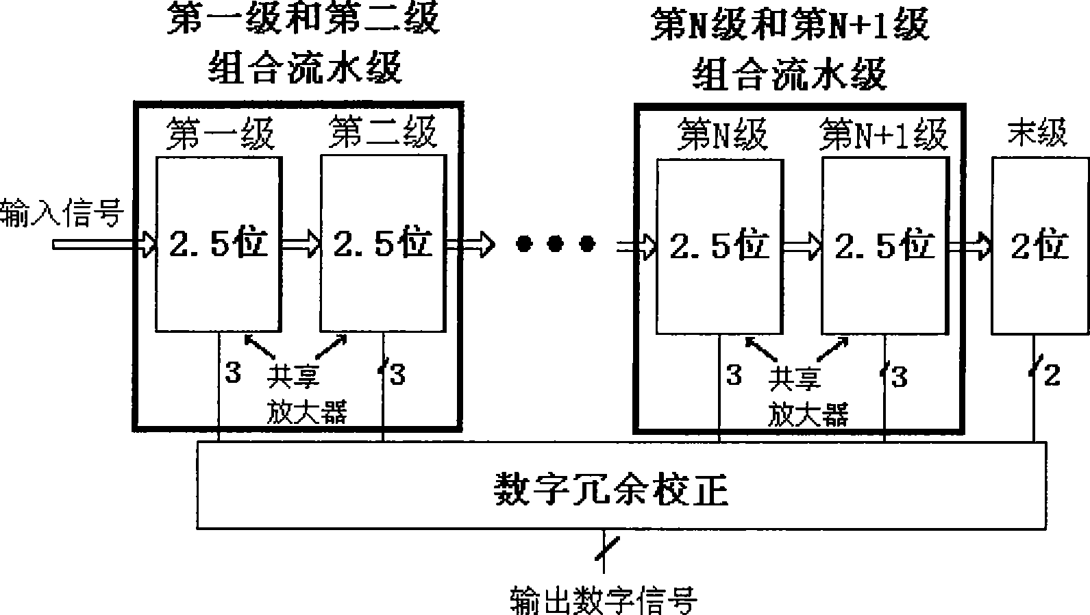
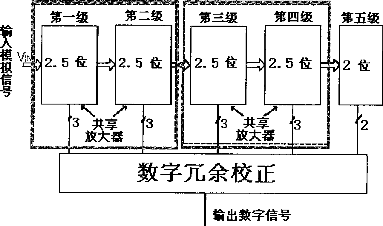
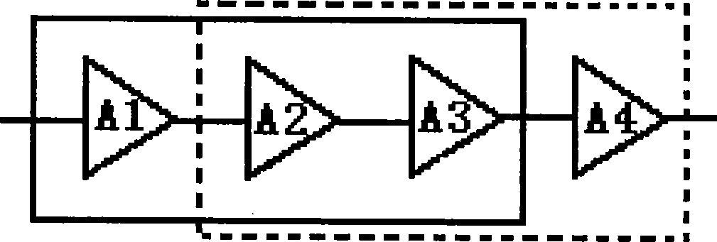
The invention discloses an analog-digital converter circuit adopting the partial multiplex technique of a multistage amplifier. The analog-digital converter consists of a flash structure and at least one combination flow stage. The flash structure is taken as the last stage of the flow stages, and the combination flow stage comprises a first flow stage and a second flow stage, wherein, the first flow stage consists of a first stage sub-amplifier A1, a second stage sub-amplifier A2, and a third stage sub-amplifier A3 in series sequentially; the second flow stage consists of a second stage sub-amplifier A2, a third stage sub-amplifier A3, and a fourth stage sub-amplifier A4 in series sequentially; and the second stage sub-amplifier A2 and the third stage sub-amplifier A3 are shared by the first flow stage and the second flow stage. By adopting the analog-digital converter circuit, the consumption of an amplifier and a system thereof is cut, and the design complexity and the dynamic performance are reduced.

Description

technical field [0001] The invention relates to the technical field of pipeline analog-to-digital converter circuits, in particular to a low-voltage, low-power consumption analog-to-digital converter circuit using a multi-stage amplifier partial multiplexing technology. Background technique [0002] In the past two decades, my country's economic growth rate was as high as 9.7%, while the energy consumption growth rate was 4.6%, which was far lower than the economic growth rate. In the next few years, the economy will still maintain a momentum of rapid growth, and energy demand will also continue to rise. With the gradual deepening of awareness of local and even global environmental problems caused by energy use, China is facing greater environmental pressure. [0003] The "National Medium and Long-Term Science and Technology Development Program Outline" promulgated on December 30, 2005 expounded the development goals of my country's high-tech industries and energy industrie...

Claims


Application Information

Patent Timeline
Patent Type & Authority Applications(China)
IPC IPC(8): H03M1/12H03F1/02
Inventor 王晗叶青
Owner SOI MICRO CO LTD
Learn More