
Digitalized automatic frequency correction method based on true frequency reference signal

A technology of automatic frequency correction and reference signal, which can be used in automatic frequency control components, electrical characteristic frequency control, communication between multiple stations, etc., and can solve the problem of high complexity

Inactive Publication Date: 2009-07-01
COMBA TELECOM SYST CHINA LTD
View PDF2 Cites 10 Cited by
  • Summary
  • Abstract
  • Description
  • Claims
  • Application Information

AI Technical Summary

Problems solved by technology

[0010] The object of the present invention is to provide a digital automatic frequency correction method based on a real frequency reference signal in order to overcome the above-mentioned shortcomings of high complexity of the digital automatic frequency correction method based on the complex frequency reference signal

Method used


Image

  • Digitalized automatic frequency correction method based on true frequency reference signal
  • Digitalized automatic frequency correction method based on true frequency reference signal
  • Digitalized automatic frequency correction method based on true frequency reference signal

Examples


Embodiment Construction

[0034] Below in conjunction with accompanying drawing, specific embodiment of the present invention and principle are described in detail:

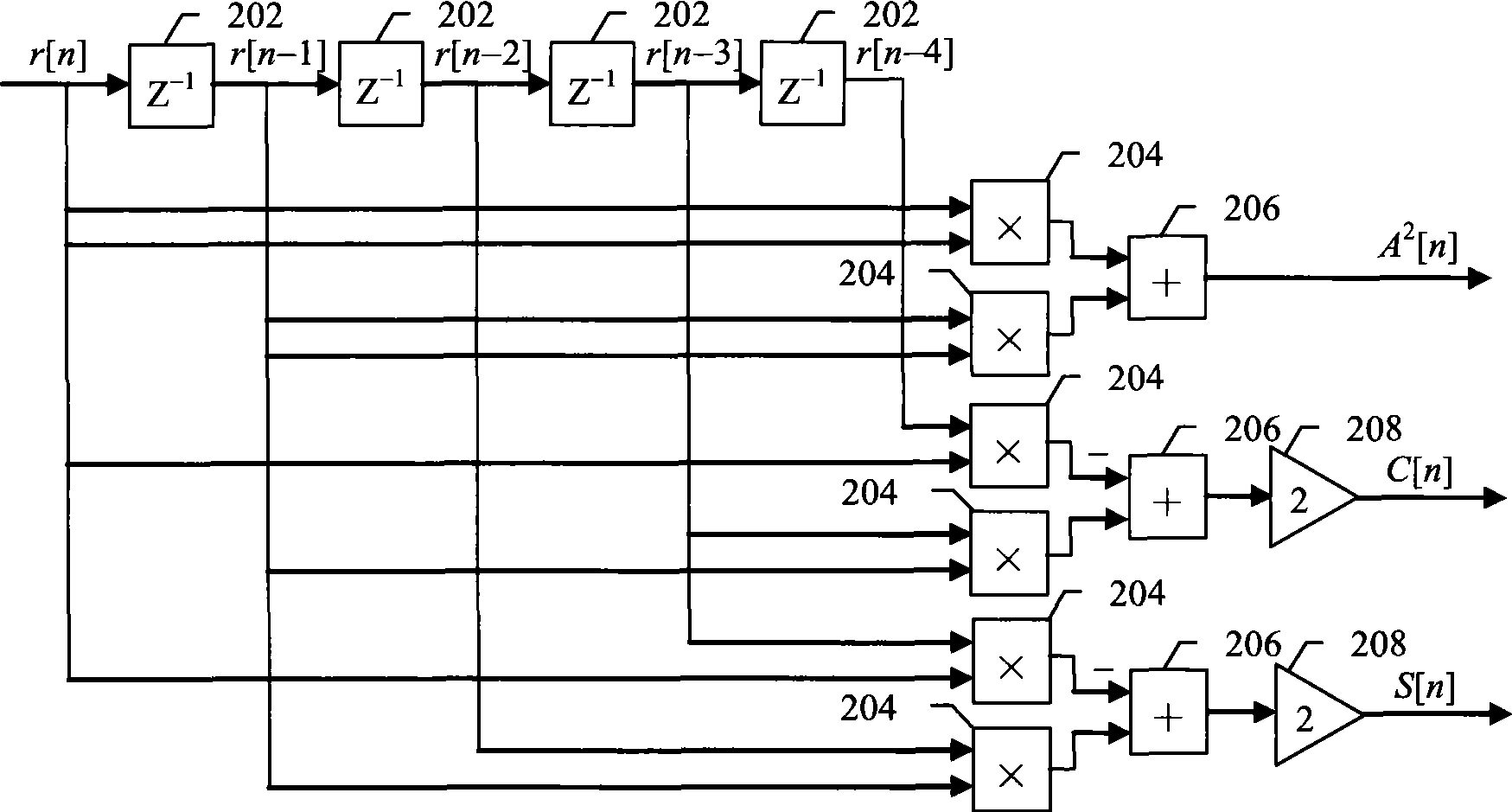
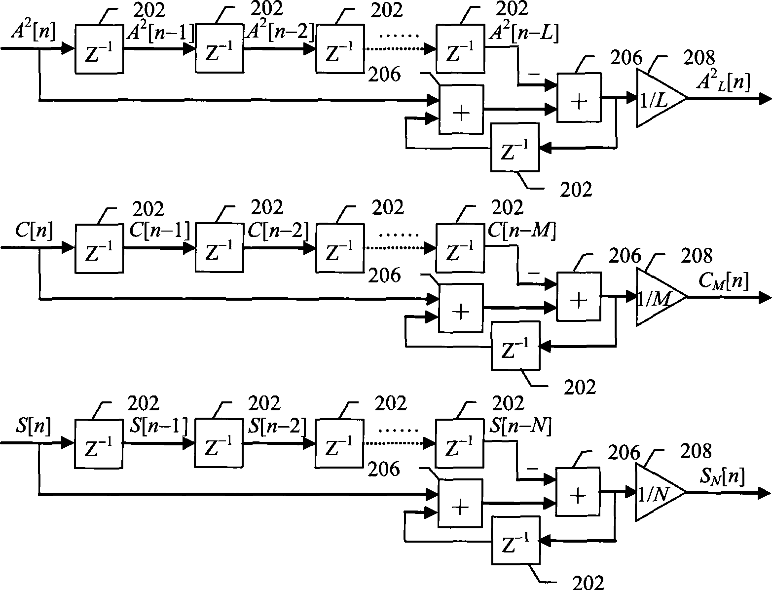
[0035] Such as figure 1 As shown, the digital automatic frequency correction method based on the real frequency reference signal of the present invention is implemented together with the digital automatic frequency detection method based on the real signal which is protected by the applicant in another application and disclosed in this application, Including A / D converter (that is, analog-to-digital converter) 102, automatic frequency and correction algorithm module 104, D / A converter (that is, digital-to-analog converter) 106, low-pass filter 108, voltage-controlled oscillator 110 and frequency divider / multiplier 112 .

[0036] exist figure 1 In , the received analog real signal r(t) comes from the intermediate frequency or baseband output of the transmitter. r(t) undergoes sampling and analog-to-digital conversion by the A / D converte...


PUM


Abstract

The invention discloses a digital automatic frequency correction method based on real frequency reference signals, which relates to the technical field of frequency synchronization of a transiting side and a receiving side in communication. The method comprises the following steps: sampling a channel of real received signals; under the condition that the real frequency reference signal exists in the received signals, calculating the frequency error function of the local frequency source signal and the received frequency reference signal; correcting the frequency of the local frequency source according to the frequency error function, thereby achieving the frequency synchronization between the transiting side and the receiving side. Compared with the prior frequency correction method based on complex frequency reference signals, the digital automatic frequency correction method doesn't need to acquire the mutually-orthogonal complex frequency reference signals of the channel I and the channel Q; overcomes the problem of imbalance compensation of the channel I and the channel Q; and therefore, greatly reduces the complexity of system implementation on the premise of ensuring the frequency correction accuracy.

Description

【Technical field】 [0001] The invention relates to a frequency synchronization system in the field of communication transmission, in particular to a digital automatic frequency correction method based on a real frequency reference signal. 【Background technique】 [0002] In a communication transmission system, the frequency of the frequency source signal at the receiving end usually needs to be consistent with the frequency of the frequency source signal at the transmitting end. In order to do this, one method that can be adopted is to use high-precision crystal oscillators at both ends of the transceiver. However, high-precision crystal oscillators are usually expensive, and frequency drift will occur after long-term use, requiring regular manual frequency correction. [0003] Another method that can be used is to send a frequency reference signal (also known as a frequency calibration signal or pilot signal) from the transmitter to the receiver, and the receiver automatical...

Claims


Application Information

Patent Timeline
IPC IPC(8): H04B7/26H04B1/707H03J7/04
Inventor 窦怀宇
Owner COMBA TELECOM SYST CHINA LTD
Learn More