
Power conversion apparatus

A power conversion device and conversion technology, which are applied to output power conversion devices, electrical components, and irreversible DC power input into AC power output, etc., can solve problems such as increasing impedance, increasing the number of components, and increasing costs. , to achieve the effect of stable action

Inactive Publication Date: 2009-07-01
MITSUBISHI ELECTRIC CORP
View PDF2 Cites 9 Cited by
  • Summary
  • Abstract
  • Description
  • Claims
  • Application Information

AI Technical Summary

Problems solved by technology

[0007] In order to effectively suppress the common mode noise current flowing into the control section, it is considered to take the following countermeasures: increase the impedance to the common mode noise current of the voltage detector and current detector respectively provided on the input side and output side of the inverter circuit, or increase the configuration The impedance of the isolation amplifier on the input side of the control section of the inverter circuit is controlled, but taking this countermeasure will lead to an increase in the size of components, an increase in the number of components, and an increase in cost, etc.

Method used


Image

  • Power conversion apparatus
  • Power conversion apparatus
  • Power conversion apparatus

Examples


Embodiment approach 1

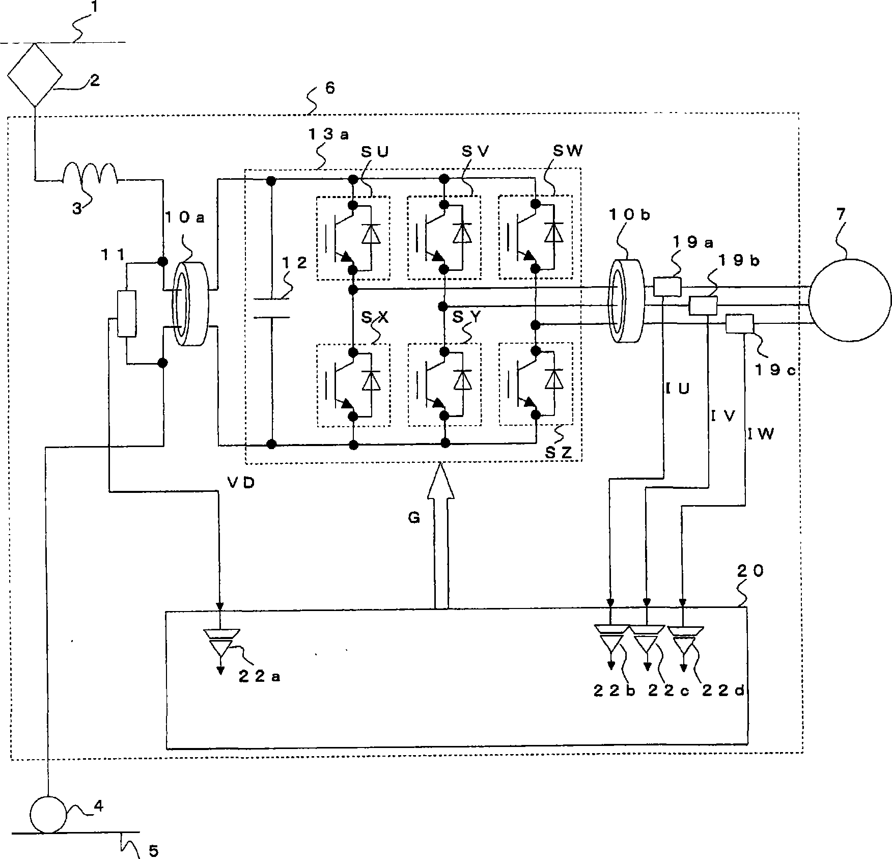
[0050] figure 1 It is a configuration diagram of the power conversion device according to Embodiment 1 of the present invention, and the same reference numerals are assigned to the same or corresponding parts as the technology on which the invention is based.

[0051] In the above-mentioned invention basic technology 1, the voltage detector 11 is connected to the input side conductor of the inverter module 13b on the output side of the first magnetic core 10a, that is, the inverter module 13b side of the first magnetic core 10a, but the present invention In the power conversion device according to Embodiment 1, such as figure 1 As shown, the voltage detector 11 is connected to the input side conductor of the inverter module 13b on the input side of the first magnetic core 10a, that is, on the side opposite to the inverter module 13b side of the first magnetic core 10a. Since the first magnetic core 10a has impedance only to the common mode noise current, even if the voltage d...

Embodiment approach 2

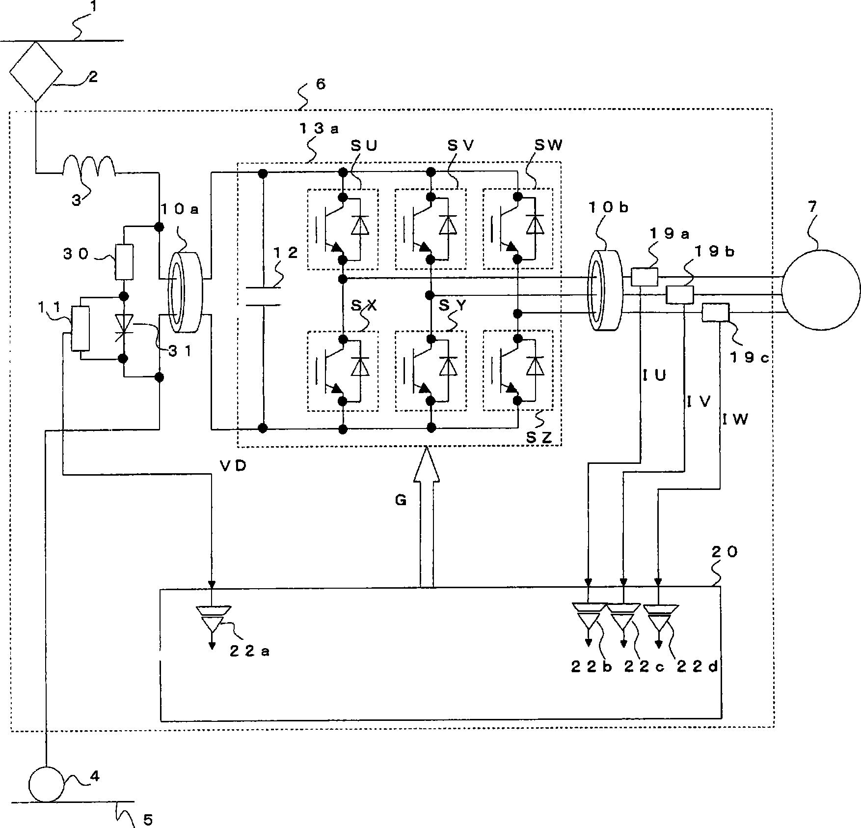
[0057] figure 2 is a configuration diagram of a power conversion device in Embodiment 2 of the present invention, figure 2 Among them, the discharge resistor 30 and the discharge element 31 are connected in series, and they constitute an overvoltage suppression discharge circuit. This overvoltage suppression discharge circuit is connected in parallel with the capacitor 12 . The voltage detector 11 is connected to both ends of the discharge element 31 .

[0058] In the above-mentioned invention basic technology 2, the voltage detector 11 is arranged on the output side of the first magnetic core 10a, but in the power conversion device according to Embodiment 2 of the present invention, as figure 2 As shown, the voltage detector 11 is arranged on the input side of the first magnetic core 10a. Since the first magnetic core 10a has resistance only to the common mode noise current, the voltage across the capacitor 12 can be detected even if the voltage detector 11 is disposed ...


PUM


Abstract

A power converter includes: a capacitor (12) connected to the input side of an inverter circuit (13a); noise suppression means (10a, 10b) arranged at least one of an input side conductor connected to the input side of the inverter circuit (13a) and an output side conductor connected to the output side of the inverter circuit (13a); quantity-of-electricity detectors (11, 19a, 19b, 19c) arranged at the input side conductor or the output side conductor at the opposite side of the inverter circuit of the noise suppression means (10a, 10b); and a control unit (20) for controlling the inverter circuit (13b) according to a quantity-of-electricity detection signal from the quantity-of-electricity detectors. The power converter can suppress the common mode noise without increasing the parts size, the number of parts, or the cost.

Description

technical field [0001] The present invention relates to a power conversion device having an inverter circuit that converts DC power supplied to an input side into AC power and supplies it to a load connected to the AC side. Background technique [0002] Conventionally, in many industrial fields such as trains and automobiles, power conversion devices having inverter circuits composed of semiconductor switching elements have been widely used. For example, there is a power conversion device that has an inverter circuit that is mounted on an electric car, connects the input side to an overhead line through a current collector, and connects the output side to a main motor that drives the electric car. The input-side conductor and the output-side conductor of the circuit are provided with magnetic cores made of magnetic materials for noise suppression (for example, refer to Patent Document 1). [0003] Also, among the power conversion devices mounted on electric cars, there is a...

Claims


Application Information

Patent Timeline
IPC IPC(8): H02M7/48
CPCH02M1/12H02M2001/123H02M1/123
Inventor 北中英俊
Owner MITSUBISHI ELECTRIC CORP
Learn More