Single sheet type sheet metal roll coating mechanism

A metal sheet, single-sheet technology, applied in the direction of coating, liquid coating device on the surface, etc., can solve the problem that the surface quality of the coating can only be coated on one side, the roller coating of the single plate is not synchronized, and the supporting point of the thin plate Short distance and other problems can achieve the effect of reducing sticking phenomenon, stable coating quality and reducing equipment loss

Inactive Publication Date: 2009-07-08
BEIJING STAR RIVER INTEGRATED EQUIP TECH
View PDF1 Cites 13 Cited by
  • Summary
  • Abstract
  • Description
  • Claims
  • Application Information

AI Technical Summary

Problems solved by technology

[0003] In order to solve the asynchronous conveying of single plate roller coating, especially in the conveying process of double-sided roller coating after the coating machine, due to the short curing time and the short distance between the supporting points of thin plate conveying, the surface quality of the coating damaged by the support sticky material can only be coated on one side. Coating and other problems, the present invention adopts a new type of single-sheet metal plate roller coating mechanism, adopts a unique structure, overcomes the above-mentioned problems

Method used


Image

  • Single sheet type sheet metal roll coating mechanism
  • Single sheet type sheet metal roll coating mechanism
  • Single sheet type sheet metal roll coating mechanism

Examples


Embodiment 1

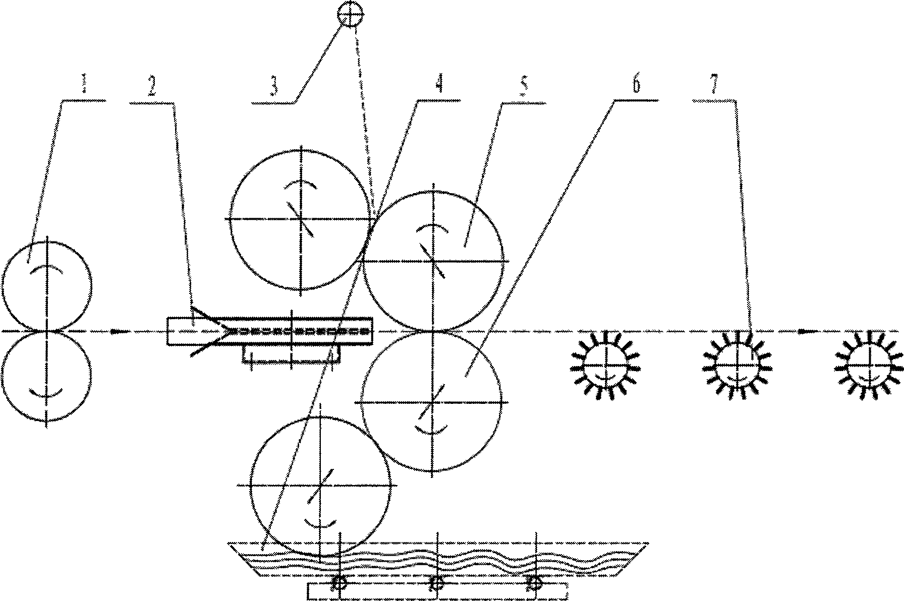
[0017] In embodiment 1: in appending figure 1 Among them, including the electrical control system, the equipment is composed of a pair of pinch rollers 1, a material guide part 2, a veneer roller coater, and a pin-wheel conveyor 7. The electrical part controls the pinch roller 1 to operate synchronously with the veneer roller coater and the pin wheel conveyor 7, which is conducive to the stable quality of the steel plate coating, and effectively controls the thickness and quality of the coating according to the coating thickness. The front end of the material guide part is made into a bell-mouth structure, and the bottom part can be a non-powered roller. The raw steel plate can pass through the material guide part directly, or the contact with the formed roller is rolling friction. In this way, the material guide part roller and the steel plate The friction force is small, and the required energy consumption is less. The pin wheel type conveying 7 is composed of a pin type rol...

Embodiment 2

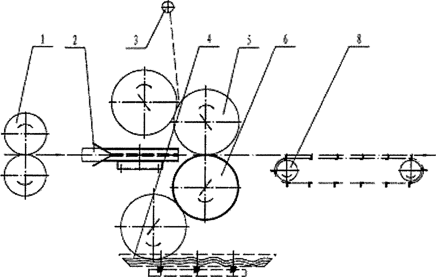
[0019] In embodiment 2: in the attached figure 2 Among them, including the electrical control system, the equipment is composed of a pair of pinch rollers 1, a material guide part 2, a veneer roller coater, and a chain conveyor 8. The electrical part controls the pinch roller 1 to operate synchronously with the veneer roller coater and the pin wheel chain conveyor 8, which is conducive to the stable quality of the steel plate coating, and effectively controls the thickness and quality of the coating according to the coating thickness. The front end of the material guide part is made into a bell-mouth structure, and the bottom part can be a non-powered roller. The raw steel plate can pass through the material guide part directly, or the contact with the formed roller is rolling friction. In this way, the material guide part roller and the steel plate Less friction and less energy required. The chain conveyor 8 is composed of a sprocket pair, and multiple rows of chains are ev...


PUM


Abstract

The invention provides a single metal sheet roller coating mechanism, which is applicable to coating of chemical coatings. The invention is characterized in that the roller coating mechanism consists of a pair of pinch rolls 1, a material guiding section 2, a single-sheet roller coater, a pin-wheel-type conveyer 7 or a chain-type conveyer 8. An electric appliance is used to control synchronization of speed of the adopted pinch rolls 1, the single-sheet roller coater, the pin-wheel-type conveyer 7 or the chain-type conveyer 8, thereby ensuring coating quality. Inlet of the material guiding section 2 is provided with a horn-mouth-type structure, so as to facilitate leading in of steel plates; the material guiding section 2 and the steel plate can contact in a rolling way or a sliding way. The incoming materials can be carried by a lacquer disc or be sprayed by a spray nozzle on a spray tube. Each roller can be adjusted jointly or individually. A lower rolling system 6 can be rapidly adjusted by an oil cylinder. Such a structure mode can realize double-surface coating, thereby reducing material sticking to the maximum. Synchronization of front and rear conveying can ensure coating quality, save time and improve production efficiency.

Description

technical field [0001] The invention belongs to a roller coating mechanism for applying a chemical coating, in particular to a roller coating mechanism for single-sheet metal plates. Background technique [0002] In the prior art, because there is no tension before and after the single sheet steel roller coating, the conveying distance between the roller coater and the rear of the machine is relatively close, and the coating is not completely dry, so the requirements for the front and rear conveying are relatively high. Most plate roller coatings have the problem of post-coating transportation. The transportation is not synchronized with the roller coating machine and the curing time of the coating after coating is short, while the distance between the roller coating machine and the post-machine transportation is relatively close, resulting in damage to the coating, or only one coating One side, not double sided. The application date is 2001.3.29, and the announcement date ...

Claims


Application Information

Patent Timeline
Patent Type & Authority Applications(China)
IPC IPC(8): B05C1/12B05C13/02B05C11/10
Inventor 汪为健
Owner BEIJING STAR RIVER INTEGRATED EQUIP TECH
Why Eureka
Try Eureka