
Electric spark clearance discharge condition detection apparatus and method based on wavelet transformation

A technology of wavelet transformation and discharge state, which is applied in the direction of measuring/indicating equipment, metal processing machinery parts, metal processing equipment, etc., to achieve high stability and strict timing effects

Active Publication Date: 2009-07-08
SHANGHAI JIAO TONG UNIV
View PDF0 Cites 11 Cited by
  • Summary
  • Abstract
  • Description
  • Claims
  • Application Information

AI Technical Summary

Problems solved by technology

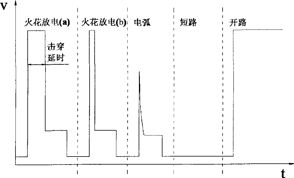
However, due to the complexity and randomness of EDM, this assumption cannot be guaranteed, and there is still a certain gap between the transformation results obtained through the idealized discharge model and the actual application.

Method used


Image

  • Electric spark clearance discharge condition detection apparatus and method based on wavelet transformation
  • Electric spark clearance discharge condition detection apparatus and method based on wavelet transformation
  • Electric spark clearance discharge condition detection apparatus and method based on wavelet transformation

Examples


Embodiment 1

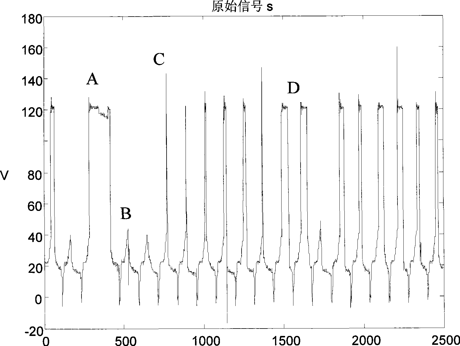
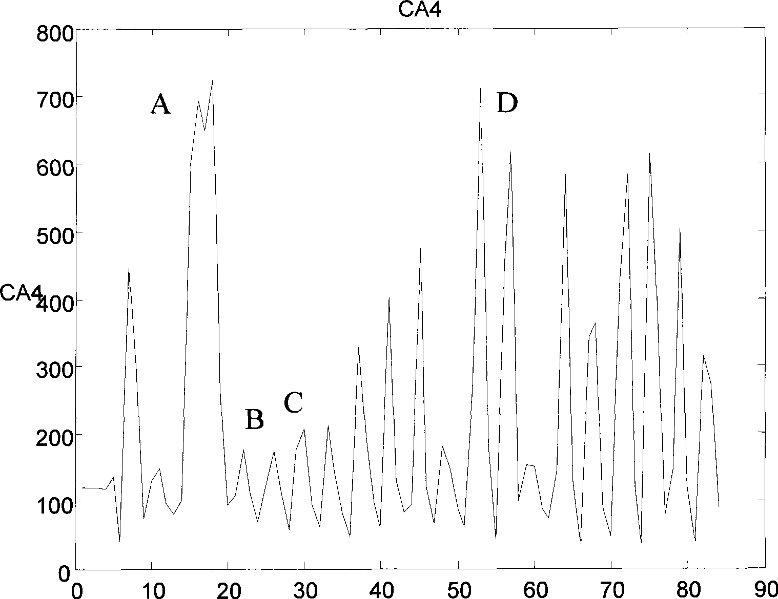
[0062] like figure 2 , 3 shown in figure 2 In the waveform diagram of the original signal s, there is a pulse at A that fails to break down and form a discharge, that is, an "open circuit" pulse appears, and the corresponding image 3 The low-frequency coefficients of CA4 in the fourth layer of wavelet transform results show a large local minimum. figure 2 There are two pulses at middle B that fail to reach the breakdown voltage and discharge first. There is no breakdown delay, and there may be arcing. This is in image 3 There are two small local maxima in . figure 2 There is a pulse with a very small breakdown delay at C in the middle image 3 There is also a correspondingly small local maximum in . figure 2 The two pulses at D in the middle have a larger breakdown delay and are better discharge pulses. They are in image 3 Corresponding to two larger local maxima. It can be seen that the condition of each pulse can be effectively judged by the wavelet transform ...

Embodiment 2

[0069] like Figure 4 and Figure 5 As shown, where the local maximum threshold MAXth=250, the local minimum threshold MINth=350, the total number of pulses Pa=20, the number of partial open pulses Po=1, the number of partial short circuit pulses Ps=12, the discharge state coefficient c=0.45 .

Embodiment 3

[0071] like Figure 6 and Figure 7 As shown, the local maximum threshold MAXth=250, the local minimum threshold MINth=350, the total number of pulses Pa=20, the partial open circuit pulse number Po=8, the partial short circuit pulse number Ps=6, and the discharge state coefficient c=1.10.


PUM

PropertyMeasurementUnit
electrical bandwidthaaaaaaaaaa

Abstract

The present invention relates to an electric spark clearance discharge condition detector which is in the special processing field and is based on wavelet transformation and a method thereof, wherein an analog optical coupler is connected with an electric spark machine tool through an inter-pole voltage signal outgoing cable. An analog-to-digital conversion module is connected at the back end of analog optical coupler. A DSP is connected at the back end of analog-to-digital conversion module. A CPLD is connected with the DSP, the USB interface and an SDRAM. A FLASH memory is connected with the DSP. The USB interface is connected with an upper machine through USB cable. The analog-to-digital conversion module samples the inter-pole voltage signal in electric spark machining and executes wavelet transformation procession to the signal in DSP. The wavelet coefficient comprising discharge condition information is obtained. The discharge condition of prior electric spark machining is obtained through the classifying decision and statistics summation of maximal value and minimum value of wavelet coefficient. The discharge condition of prior electric spark machining is transmitted to an upper machine. The electric spark clearance discharge condition detector of the invention has the advantages of excellent real-time property, excellent stability, excellent reliability, excellent accuracy and wide application sphere.

Description

technical field [0001] The invention relates to a detection device and method in the technical field of special processing, in particular to a detection device and method for electric spark gap discharge state based on wavelet transform. Background technique [0002] EDM uses pulsed spark discharge between the tool electrode and the workpiece to etch the material on the surface of the workpiece, and finally copies the shape of the electrode to the workpiece in reverse. This processing method is not affected by the mechanical properties of the workpiece material such as strength and hardness With the advantages of limited and no macro cutting force, it is especially suitable for processing difficult-to-machine materials and workpieces with complex shapes. It has a wide range of applications in aviation, aerospace, automobiles, electronics, molds and other industries. [0003] The inter-electrode voltage signal in EDM reflects the complex environment between electrodes during ...

Claims


Application Information

Patent Timeline
Patent Type & Authority Applications(China)
IPC IPC(8): B23Q17/09B23H1/00
Inventor 赵万生蒋毅康小明顾琳
Owner SHANGHAI JIAO TONG UNIV
Learn More