Mechanical arm

A technology of a robot arm and body, applied in the field of robot arms with supporting components, which can solve the problems of insufficient height of the supporting glass substrate, easy wear of the vacuum pad, and increased manufacturing cost, so as to improve convenience, avoid dirt adhesion, and disassembly convenient effect

Inactive Publication Date: 2009-07-08
AU OPTRONICS CORP
View PDF0 Cites 0 Cited by
  • Summary
  • Abstract
  • Description
  • Claims
  • Application Information

AI Technical Summary

Problems solved by technology

[0007] In view of the above problems, the purpose of the present invention is to provide a mechanical arm, which solves the problem that the vacuum pad in the prior art is prone to wear, and the height of the supporting glass substrate is insufficient, so dirt is easily attached to the glass substrate. Problems that lead to increased manufacturing costs

Method used


Image

  • Mechanical arm
  • Mechanical arm
  • Mechanical arm

Examples


Embodiment Construction

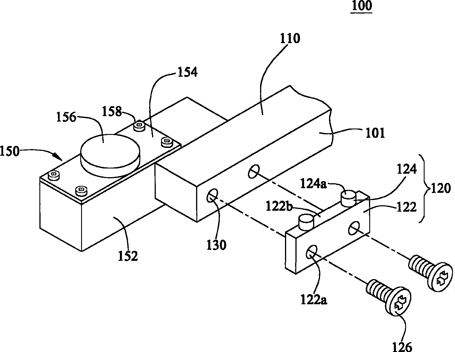
[0031] image 3 It is an exploded schematic diagram of a mechanical arm according to the present invention, Figure 4 for image 3 stereogram of Figure 5 for image 3 side view. see image 3 , Figure 4 and Figure 5 , the robot arm 100 of this embodiment is used to carry a plate 200 . Wherein, the panel 200 disclosed in the present invention can be a fragile electronic semi-finished product such as a glass substrate, a circuit board, a chip, etc., but is not limited thereto. In the following detailed description of the present invention, a glass substrate will be used as a preferred embodiment of the present invention. However, the drawings are only for reference and illustration, and are not intended to limit the protection scope of the present invention.

[0032] The robotic arm 100 includes an arm 101 and a support member 120 , and the upper surface of the arm 101 is a receiving surface 110 . The support member 120 is mounted on one side of the support arm, and t...


PUM


Abstract

The present invention relates to a mechanical arm which is used for carrying a plate. The mechanical arm comprises the following components: at least one supporting arm which is provided with a receiving surface; and a supporting component. The supporting component is provided with a body and at least one contact pad, wherein the body is installed at side edge of supporting arm. The contact pad is installed on the body. Furthermore the contact pad is relatively higher than the receiving surface of supporting arm for the placing of plate. The mechanical arm of the invention can effectively reduce the manufacturing cost and facilitates the manufacturing process. Additionally, as the contact pad of the invention and the body are integratedly molded, the detachment is quite convenient and the using facility can be increased.

Description

technical field [0001] The present invention relates to a mechanical arm, and in particular to a mechanical arm with a support member for carrying a board. Background technique [0002] In the manufacturing process of liquid crystal display, the glass substrate is one of the key components, and it is used as the carrier of related processes, such as cleaning, thin film, exposure, development, etching, electrical setting of integrated circuit components, and cutting processes. After one or several processes are completed, the glass substrate is transported by the robot arm to the next process machine for subsequent process steps of liquid crystal display panel (LCD). [0003] figure 1 and figure 2 It is an exploded schematic diagram and a side schematic diagram of an existing mechanical arm. As shown in the figure, the existing robotic arm 10 carries a glass substrate 30 through a plurality of carrying members 20 . The bearing member 20 is mounted on the side of the robo...

Claims


Application Information

Patent Timeline
Patent Type & Authority Applications(China)
IPC IPC(8): B25J15/06
Inventor 赖志昌田壬志
Owner AU OPTRONICS CORP
Why Eureka
Try Eureka