Testing bench and apparatus for cantilever beam dynamic response under movable mass function

A moving mass, dynamic response technique used in measuring devices, vibration testing, testing of machine/structural components, etc.

Inactive Publication Date: 2009-07-08
JIAXING UNIV
View PDF0 Cites 15 Cited by
  • Summary
  • Abstract
  • Description
  • Claims
  • Application Information

AI Technical Summary

Problems solved by technology

In the second type of model, there is still a gap in the experimental research on the influence of the moving mass and moving speed parameter changes of the moving load on the dynamic response of the elastic beam.

Method used


Image

  • Testing bench and apparatus for cantilever beam dynamic response under movable mass function
  • Testing bench and apparatus for cantilever beam dynamic response under movable mass function

Examples


Embodiment Construction

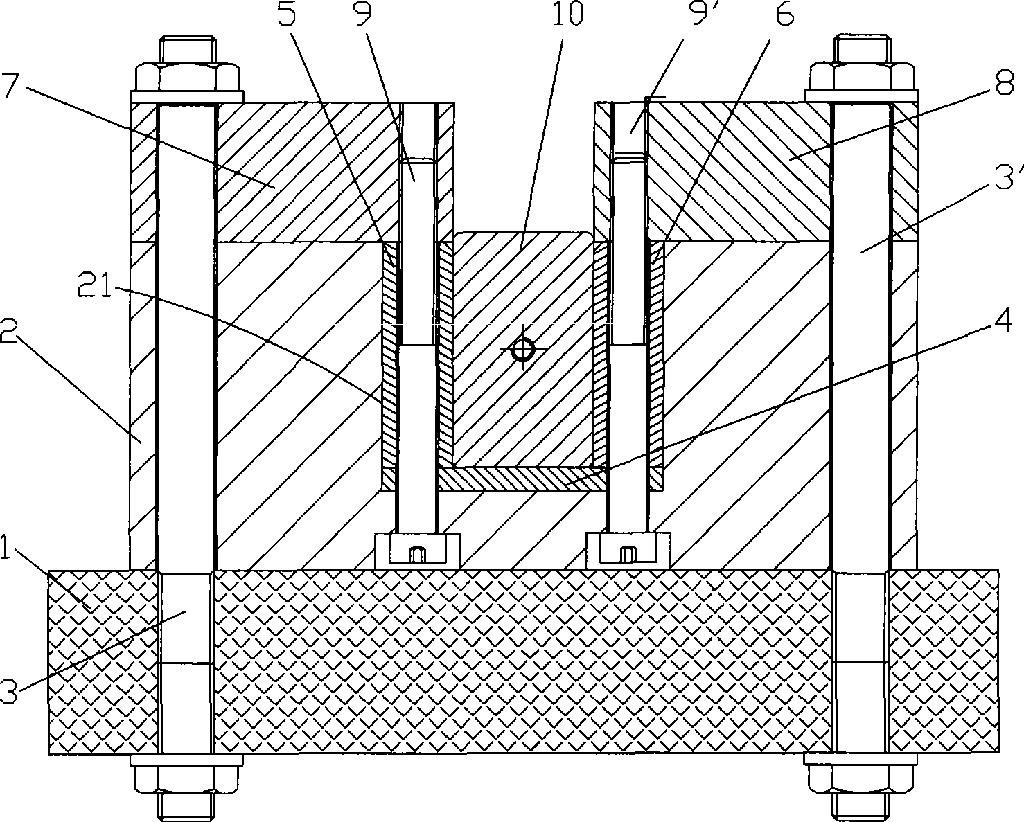
[0016] see figure 1 , a cantilever beam dynamic response test bench under the action of a moving mass of the present invention, which includes a base 1, a lower plate 2, fixed on the base 1 by two studs 3, 3' and nuts, the The center of the lower plate 2 is provided with a groove 21; a cantilever beam 4, one end of which is arranged at the bottom of the groove 21 of the lower plate 2, and the other end is a free end; left and right guide rails 5, 6 are respectively arranged on the lower plate 2 The inner wall on both sides of the groove 21; the left and right upper plates 7, 8 are arranged on the lower plate 2 and the left and right guide rails 5, 6 respectively, and the lower plate 2 and the lower plate are arranged on the lower plate by screws 9, 9' 2 The cantilever beam 4 in the groove 21, the left and right guide rails 5, 6, the left and right upper plates 7, 8 are connected and fixed; the mass block 10 is slidably arranged on the upper end surface of the cantilever beam 4...


PUM


Abstract

The invention relates to a dynamic response testing device for a cantilever beam under the action of moving mass. The device comprises a test bench, a cantilever beam, a left guide rail, a right guide rail, a left upper plate, a right upper plate, a mass block, a motion generation device, an acceleration sensor, a displacement sensor, a strain and current vortex displacement sensor, wherein the test bench comprises a pedestal and a lower plate fixed on the pedestal; the center of the lower plate is provided with a groove; one end of the cantilever beam is arranged in the groove of the lower plate; one end of the left guide rail and one end of the right guide rail are arranged in the groove of the lower plate; the left upper plate and the right upper plate are arranged on the upper parts of the left guide rail and the right guide rail; the mass block is arranged on the cantilever beam and is connected with the motion generation device; the motion generation device comprises a servo motor, a controller, a microcomputer power supply and a speed controller; the acceleration sensor is fixed on the mass block; the displacement sensor is arranged on the cantilever beam; the strain and current vortex displacement sensor is arranged on the lower end face of the cantilever beam and is in electrical connection with a signal processing system and a computer; and according to a sensor signal, the computer controls the motion form of the mass block through the adjustment of the output voltage of the microcomputer power supply. The device can be used for testing the transverse vibration property of the cantilever beam under the action of moving load and can also be further used for active control of vibration of the cantilever beam.

Description

technical field [0001] The invention relates to a test device for testing the dynamic response of a cantilever beam under the action of a moving mass, in particular to a test bench for the dynamic response of a cantilever beam under the action of a moving load and a test system thereof. Background technique [0002] There are many elastic beam structures affected by moving loads, such as vehicle-bridge system, material-pipeline system, projectile-body tube system, rocket, missile-elastic launch beam system, etc. The dynamic response of beams under coupled moving mass / load excitations is one of the most original problems in structural dynamics because of the mutual coupling between the moving mass and the elastic beam vibration system. Usually, the research on the dynamic interaction between the moving mass and the structure mostly ignores the coupling effect between the rigid body motion of the moving mass and the elastic vibration of the structure. [0003] With the contin...

Claims


Application Information

Patent Timeline
IPC IPC(8): G01M7/02
Inventor 胡红生钱苏翔
Owner JIAXING UNIV
Why Eureka
Try Eureka