
Measuring method and apparatus for mask bench scanning inclination

A measurement method and a technology of a measurement device, which are applied in the direction of photolithography exposure devices, microlithography exposure equipment, etc., can solve the problems of large random errors, consumption of glue-coated silicon wafers, and long time consumption, so as to avoid errors and reduce energy consumption. time, the effect of simplifying the measurement process

Active Publication Date: 2009-07-08
SHANGHAI MICRO ELECTRONICS EQUIP (GRP) CO LTD
View PDF0 Cites 13 Cited by
  • Summary
  • Abstract
  • Description
  • Claims
  • Application Information

AI Technical Summary

Problems solved by technology

[0006] However, in the prior art, using the exposure method to measure the scanning tilt needs to consume a rubber-coated silicon wafer, and at the same time, reading the focal plane at different positions of the mask stage under an optical microscope will bring large random errors
In addition, the method of measuring the scanning tilt of the mask stage in the prior art as mentioned above needs to go through the steps of gluing, exposure, development, reading, fitting calculation, etc., which takes a long time

Method used


Image

  • Measuring method and apparatus for mask bench scanning inclination
  • Measuring method and apparatus for mask bench scanning inclination
  • Measuring method and apparatus for mask bench scanning inclination

Examples


Embodiment Construction

[0022] The method and device for measuring the scanning tilt of the mask stage of the present invention will be further described in detail in conjunction with embodiments below.

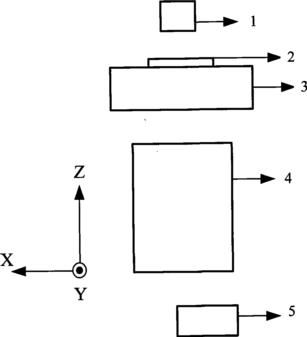
[0023] see image 3 A schematic structural diagram of a lithography machine system is shown, and the lithography machine system includes: an exposure light source 1 , a mask table 3 carrying a test mask 2 , a projection objective lens 4 and an image sensor system 5 .

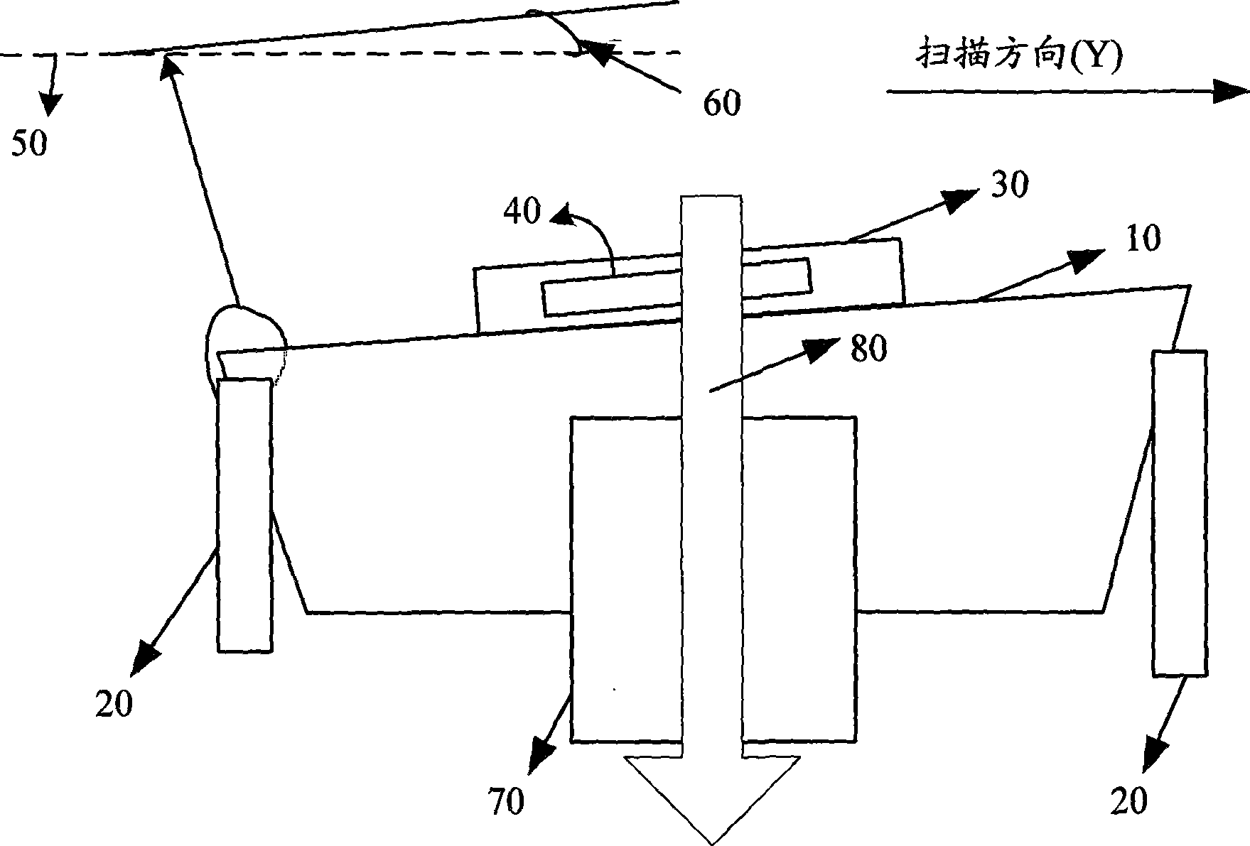
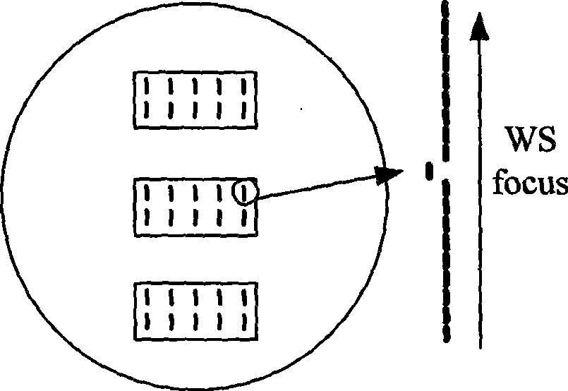
[0024] Next, please combine Figure 4 , which shows a schematic diagram of the process of measuring the scanning tilt of the mask stage in the present invention. As shown in the figure, the test mask 2 can move along the scanning direction (Y direction) of the mask table driven by the mask table 3, and the movement can be forward or reverse. There are a plurality of alignment marks 20 on the test mask 2, and the structure of these alignment marks can be as follows figure 2 As shown, other marking structures can also be used, mainl...


PUM


Abstract

The invention provides a method and a device for measuring oblique scan of a mask platform. The method comprises: firstly, laying a test mask on the mask platform, wherein a plurality of rows of aligning marks are arranged on the test mask; secondly, moving the mask platform, and making a row of aligning marks on the test mask positioned in the center of a visual field of an exposed light source system; thirdly, opening exposed light sources, and making a plurality of aligning marks imaged below a projection objective; fourthly, horizontally and vertically moving an image sensor system, and scanning space images of the row of aligning marks so as to acquire the height difference Zf of vertical positions of the space images of the aligning marks opposite to a focal plane of an image space of the projection objective; fifthly, converting the Zf into the height difference Zi of the vertical positions of the aligning marks opposite to a focal plane of an object space of the projection objective; sixthly, repeatedly executing the second step, the third step, the fourth step and the fifth step so as to acquire the Zi of different rows of aligning marks, and establishing a plurality of corresponding oblique scan deviation models according to the relations between the oblique scan deviation of the mask platform and the Zi; and seventhly, calculating the oblique scan deviation of the mask platform according to the plurality of the models.

Description

technical field [0001] The invention relates to a measuring method and device for a photolithography machine system, in particular to a method and a device for measuring the scanning inclination of a mask table in a photolithography machine system. Background technique [0002] Such as figure 1 As shown, in the scanning exposure process of the lithography machine system, the height of the mask table 10 is controlled by three actuators 20 (for simplicity, figure 1 Only two actuators are shown in the figure), the plate holder 30 carries the mask 40 and moves along the scanning direction of the mask table (ie, the Y direction) on the marble upper surface of the mask table 10 . [0003] However, due to the limitation of machining accuracy, the marble upper surface of the mask table 10 is not ideally parallel to the optimum object plane 50 of the projection objective lens 70, so during the scanning exposure process with the exposure light source 80, the mask it carries 40 has a...

Claims


Application Information

Patent Timeline
Patent Type & Authority Applications(China)
IPC IPC(8): G03F7/20
Inventor 江传亮
Owner SHANGHAI MICRO ELECTRONICS EQUIP (GRP) CO LTD
Learn More